Head Up Display (HUD) Buttons
The Head Up Display buttons are a set of function buttons which are permanently displayed in the top left or right corner of the graphic area in Designer.
![]() Note:
Note:
Positioning of the HUD buttons depends on whether the option Show command prompts in graphic area is activated or not. When this option is activated, Command prompts  are displayed in the bottom right corner of the graphic area and HUD buttons in the top right corner. When not activated, Command prompts are displayed in the top right corner and HUD buttons are displayed in the top left corner. This option is available under File > Settings > Options > User Interface.
The default configuration for HUD buttons is as shown below in Designer:
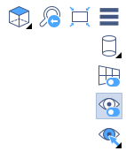
The HUD button layout can be configured to meet user requirements. A specific section on HUD Button Layout Customisation provides a detailed description about how to adapt the layout for your specific needs. This section of the Help system explains the default configuration.
HUD button functionality is a very useful tool providing immediate access to a series of functions to manipulate objects which are currently displayed in the graphic area. Such functions include orientation, size, rendering, visibility, etc.
Default Configuration Buttons
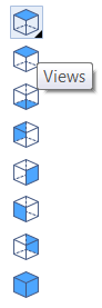
Views
![]()
Allows you to determine the orientation of the object currently displayed in the graphic area.
![]() Note:
Note:
For all HUD buttons, a small black triangle in the bottom right corner indicates that a drop-down list of alternative commands is displayed when the button is clicked.
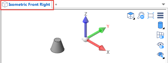
- Click on the corresponding icon to select the orientation that you want to apply (top, bottom, left, right, etc.).
- After validation, the current view is displayed as a text just above the top left corner of the graphic area:
Previous View
![]()
If a series of view orientations were performed on the current object in the graphic area, you can successively switch back to a previously selected orientation.
Include All
![]()
Automatically resizes the current object to fit in the graphic area by zooming in or out.
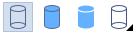
Rendering Modes
![]()
Allows the user to select the rendering mode to be applied to the object in the graphic area. Click on this button to display the rendering mode options:
|
|
Displays objects in wireframe mode only. |
|
|
Displays objects in shaded mode with outlines. |
|
|
Displays objects in shaded mode without outlines. |
Orthographic / Perspective Display Switch
![]()
Switches between Orthographic and Perspective display modes.
Switch Visibility
![]()
Activating this function (highlighted button) allows you to display only the visible or hidden entities (as defined in the Attributes / Visibility functions described below) in the graphic area. As soon as you execute an Attributes / Visibility command, this function is automatically activated:
Deactivating this function displays all entities.
Attributes / Visibility
![]()
Clicking this button displays a set of command buttons to determine visible and hidden entities:

|
|
Select Visible Entities - Allows you to select individual elements / entities in the graphic area which remain displayed in the graphic area after validation (right click).
When using this command, any previously selected visible entities are cancelled. Only the ones selected during this sequence are retained for display. Using the Switch Visibility command explained above allows you to display all entities or visible entities only. |
|||
|
|
Select Invisible Entities - Works in the same way as the Select Visible Entities command described above but applies to entities that you want to make invisible. The same notes apply accordingly. | |||
|
|
Flip Visibility - Switches the display in the graphic area between visible entities and hidden entities and vice-versa.
The Switch Visibility function must be active (highlighted button) for this command to work. |
|||
|
|
Add / Delete Entities - Allows you to change hidden entities to visible ones and/or change visible entities to hidden ones in the same sequence.
When this command is run, all entities (hidden or visible) are made available for selection in the graphic area. |
|||
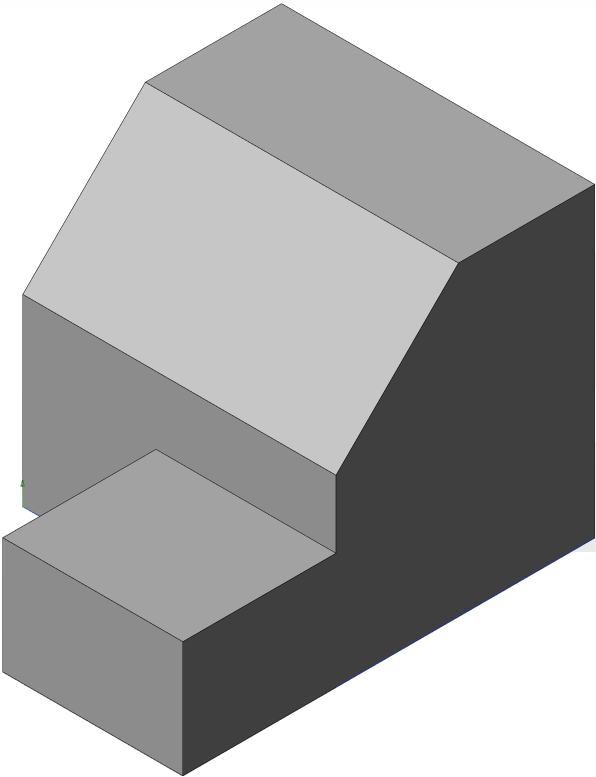
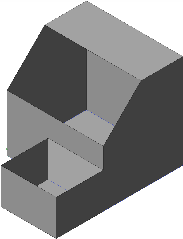
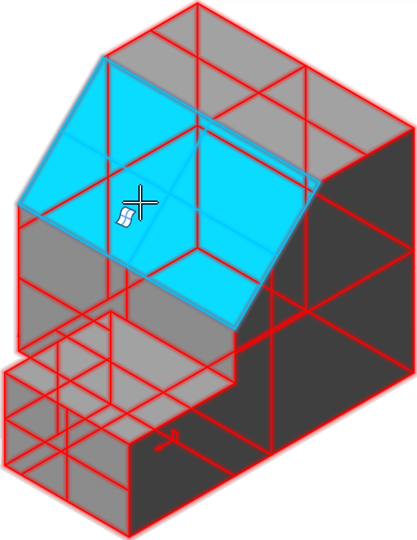
|
||||
| The first image shows all entities when the file was loaded. The second image shows the object with some hidden entities. The third image shows the graphic area contents when the Add / Delete Entities command has been run. Any selected entities (hidden or visible) will display in blue and the command will be applied after validation (right click). | ||||
|
|
Add to Visible Entities - Allows you to change hidden entities to visible ones and display them with the currently visible entities in the graphic area.
When activated, only the currently hidden entities are displayed in the graphic area. |
|||
|
|
Remove from Visible Entities - Allows you to change visible entities to hidden ones and remove them from the currently visible entities in the graphic area. | |||
For further information...