Extrude
![]()
The Extrude function allows you to create a solid by moving an element through a distance in a given direction. It also allows you to apply a taper angle to the created solid.
![]() Notes:
Notes:
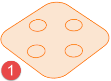
- You may select and extrude regions (closed areas generated by wireframe elements/edges that lie on the current Workplane). They are selected as faces.
- It is possible to select wireframe elements, faces, sheet bodies, edges and regions to create extrusions.
- When selecting wireframe elements such as lines or arcs, or edges from surfaces or a solid, they will be extruded as sheet elements only.
- Extruding a profile or region allows you to create a solid body.
- To create a solid body from a face or surface/sheet, use the Extrude option in the Move function.
Access
- Click the
 icon in the Designer tab of the application.
 - Activate the Modelling tab and then click the icon in the Operation section of the ribbon.
- This option may also be available in the context menu accessed by a Right Mouse click.
In all cases, this opens the Extrude elements - Options tab which is displayed along with the ribbon containing:
- The Attributes, Filters and Direction Options sections if a model element was previously selected or
- The Attributes, Selection, Filters, Options and Environments section without previous model element selection.
Procedure
- If it was not done previously, using the different selection filter options, select the elements which you want to extrude.
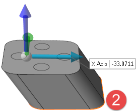
- Using the Options section of the ribbon, define the extrusion direction.
- Press the Right Mouse button to validate the direction and to display the Options - Extrude Elements dialog box.
 (See dialog box.)
- Select the required options according to the result you want to achieve.
The options in the Measurement menu section of the ribbon help you to define specific points. - Using the Distance and Taper angle sliders, their value input boxes or the corresponding fields in the dialog box, define the extrusion to apply.
- Validate, either by a Right Mouse click or by clicking the
 icon in the graphic area or in the function dialog box.
![]() Note: If mandatory values are missing or if erroneous values are entered, an exclamation mark
Note: If mandatory values are missing or if erroneous values are entered, an exclamation mark ![]() is displayed in the relevant slider value input box and the background of the corresponding parameter input box in the Options panel is displayed in red.
is displayed in the relevant slider value input box and the background of the corresponding parameter input box in the Options panel is displayed in red.
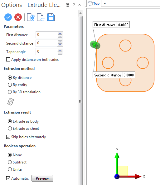
Extrude Options
The following options are available in the Options - Extrude Elements dialog box. ![]() (See dialog box.)
(See dialog box.)
Top Toolbar
![]()
![]()
![]()
![]()
![]()
![]()
![]()
![]()
![]()
From left to right, this toolbar displayed at the top of the option dialog box allows you to Apply the current values, to Cancel the current function, to Restore the system defaults and to Restore the defaults that have previously been saved using the Save icon.
Parameters
|
First distance |
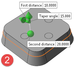
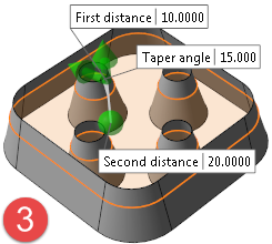
If By distance is active in the Options section of the dialog box, this field allows you to enter the first extrusion distance. Its value may be positive or negative. |
|
Second distance |
If By distance is active in the Options section of the dialog box, this field allows you to enter the second extrusion distance. Its value may be positive or negative. The field is not available if the Apply distance on both sides option has been activated. |
|
Taper angle |
This field allows you to define a taper angle. A negative angle will expand the reference element to its final size and a positive angle will decrease the size of the reference profile or element. This option also works with open wireframe elements when they are extruded using the By entity option. |
|
Apply distance on both sides |
If this option is active, the value entered for the First distance is applied on both sides of the selected elements. The Second distance field is not available. |
Extrusion Method
|
By distance |
Activate this option to define one or two extrusion distances. |
|
By entity |
Activate this option to define the extrusion length by reference entity.
|
|
By 3D translation |
This option allows you to extrude the selected elements along three directions.
|
|
|
Click this icon to enter the selection mode. By default, selection is launched in the Combined environment. |
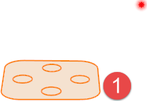
 - profile to extrude with reference point,
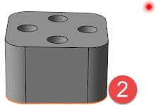
  - extruded profile
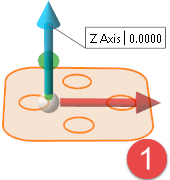
Extrusion Result
|
Extrude as body |
For profiles or regions, activating this option allows you to extrude the elements as body (see |
|
Extrude as sheet |
Activating this option allows you to extrude the elements as sheets (see |
|
Skip holes alternately |
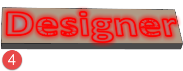
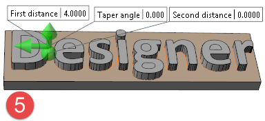
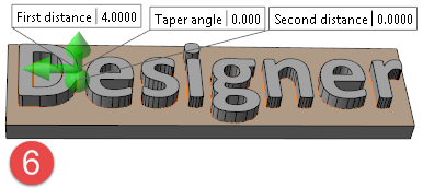
Activating this option (working with bodies and sheets) applies a simultaneous extrusion of inner and outer profiles. Only the portion included between the profiles is extruded. This option is particularly useful when extruding text for engraving purposes. In the following example, for the text profile to be extruded |
 in the following illustration).
 , this option was not active in
  and activated in
 .
.
Boolean operation
This section allows you to select a Boolean operation to apply during solid creation. Select either None, Subtract or Unite.
Preview
Preview generation is Automatic if this option is active. Otherwise, click on the Preview button to obtain a preview in the graphic area.
The field at the bottom of the Options panel displays information about missing data, errors or actions.