Cylinder
![]()
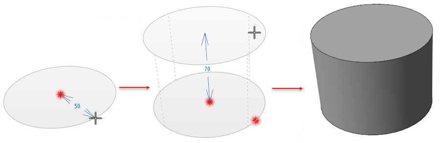
The Cylinder function is used to create a solid body by defining a centre point, radius and a certain height.
Access
- Click the drop-down arrow under the
 icon in the Designer tab of the application and select
 Cylinder.
 - Activate the Modelling tab and then click the icon in the Forms section of the ribbon.
- This option may also be available in the context menu accessed by a Right Mouse click.
In all cases, this opens the Cylinder Options tab which is displayed along with the ribbon containing the Attributes, Filters and General sections.
Procedure
In the General section of the ribbon, select whether you want the Dialog box ![]() to be displayed, where you want to select a direction
to be displayed, where you want to select a direction ![]() and, if required, the Boolean operation to apply. You may also set the Cursor grid snap distance
and, if required, the Boolean operation to apply. You may also set the Cursor grid snap distance ![]() .
.
The procedure to be followed depends on whether the Dialog box is displayed.
Dialog box option NOT active:
- If the Select direction
 option is active, click the point where you want to place the direction arrow (use the Space Bar to change direction) and Right Mouse click to validate. This point becomes the application point of the cylinder. Alternatively, in the graphic area, click on the point where you want to place the centre of the cylinder.
 - Drag the mouse until the desired radius is reached and click.
- Drag the mouse to define the height of the cylinder and click at the required point.
- Validate, either by a Right Mouse click or by clicking the
 icon in the graphic area or in the function dialog box.
The corresponding dimensions are displayed as you move the mouse. ![]() (See illustration.)
(See illustration.)
Dialog box option active:
This option offers greater control for solid creation.
- If the Select direction option is active, click the point where you want to place the direction arrow (use the Space Bar to change direction) and Right Mouse click to validate. This point becomes the centre point of the cylinder. Alternatively, in the graphic area, click on the centre point of the cylinder to display the slider along with the Options - Cylinder dialog.
 (See dialog box.)
Using the sliders in the graphic area:
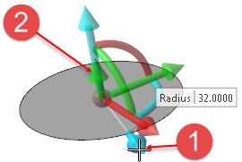
- Click and hold down the Left Mouse button on the Radius slider
 and drag it to the required radius. Click to set the radius.
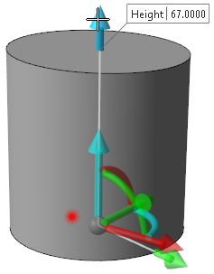
 - Using the same method, define the Height
 of the cylinder.
Clicking the active slider arrow allows you to adjust the value of the corresponding dimension in the value input box. - Validate, either by a Right Mouse click or by clicking the icon in the graphic area or in the function dialog box. (See illustration.)
![]() Note: If mandatory values are missing or if erroneous values are entered, an exclamation mark
Note: If mandatory values are missing or if erroneous values are entered, an exclamation mark ![]() is displayed in the relevant slider value input box and the background of the corresponding parameter input box in the Options panel is displayed in red.
is displayed in the relevant slider value input box and the background of the corresponding parameter input box in the Options panel is displayed in red.
Dialog Box and General Options
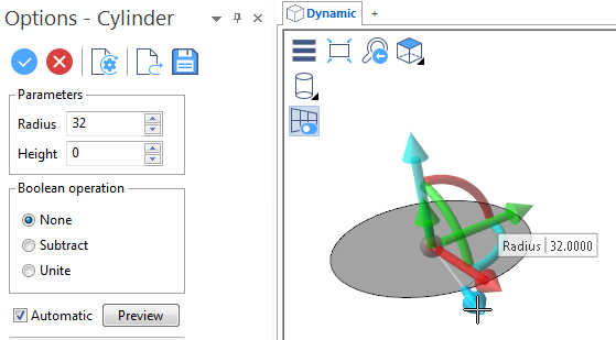
If the Dialog box option has been activated in the General section of the ribbon, the Options - Cylinder panel is displayed ![]() (see dialog box) containing the following options which are also present in the General section on the ribbon:
(see dialog box) containing the following options which are also present in the General section on the ribbon:
Top Toolbar
![]()
![]()
![]()
![]()
![]()
![]()
![]()
![]()
![]()
From left to right, this toolbar displayed at the top of the option dialog box allows you to Apply the current values, to Cancel the current function, to Restore the system defaults and to Restore the defaults that have previously been saved using the Save icon.
Parameters
The values in this section are automatically updated as you use the sliders in the graphic area. You may also manually enter or adjust the corresponding values.
Boolean operation
This section allows you to select a Boolean operation to apply during solid creation. Select either None, Subtract or Unite.
Preview
Preview generation is Automatic if this option is active. Otherwise, click on the Preview button to obtain a preview in the graphic area.
The field at the bottom of the Options panel displays information about missing data, errors or actions.