Surface by one Drive Curve and one or two Shape Curves
![]()
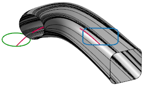
This command allows you to create a surface as the evolution of a primary shape curve towards a second shape curve along a directional or drive curve. The drive curve defines the surface shape in the longitudinal direction (the U direction of the surface), and the shape curves define the sectional shape (the V direction).
It is possible to select two different shape curves that define the surface cross-sections at each end of the drive curve, but the same command will also drive a single shape curve along the directional curve.
Access
- Click the
 icon in the Surfaces tab.
 - Type Drive in the Quick Search field and select By 1 drive from the result list.
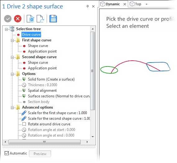
This opens the Command - By 1 drive tab which is displayed along with the ribbon containing the Filters and Attributes sections. At the same time, the 1 Drive 2 shape surface dialog box is displayed. ![]() (See dialog box.)
(See dialog box.)
Procedure
- Click the drive curve close to the end at which the first shape curve is positioned.
- Click the first shape curve and then, using the Point filters, click the application point of the first shape.
- Click the second shape curve and then, using the Point filters, click the application point of the second shape.
- Set the required options according to the result that you want to obtain.
- Validate by clicking the
 icon in the dialog box.
If you want to use only one shape curve, select the first curve again and define the required application point.
![]() Note: The application points do not need to be positioned on the shape curves.
Note: The application points do not need to be positioned on the shape curves.
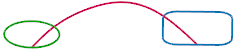
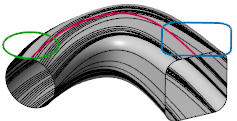
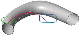
If the red drive curve is selected along with the green circle and the blue rectangle as the shape curves (application points at the intersections with the guide curve), you obtain the following result with the default settings:
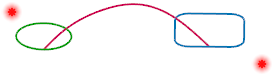
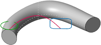
In the following example, the same entities are selected but the application points are positioned outside the curves:
1 Drive 2 Shapes Surface - Dialog Box Options
The Selection tree of the dialog box automatically guides you through the selection phase. When the corresponding entity has been selected, the red dot displayed alongside the entry switches to green. In addition, a number of options are available. ![]() (See dialog box above.)
(See dialog box above.)
|
Drive curve |
This is the first curve to be selected near to the extremity where you want the surface creation to start. It defines the longitudinal (U) direction of the surface. In the following example, the red drive curve was selected next to the blue curve and then the green circle was selected as the first shape and the rectangle as the second shape:
|
|
First shape curve |
The entries in this section allow you to define the first Shape curve and its Application point. |
|
Second shape curve |
The entries in this section allow you to define the second Shape curve and its Application point. You may reselect the first shape curve again. This has been done in the following example:
|

![]() Notes:
Notes:
- Clicking on an entry in the Selection tree highlights the corresponding entity in the graphic area.
- To modify your selection, Right Mouse click on the corresponding item and then click on Reset selection and select another entity in the graphics area.
You may also highlight the corresponding entry and then select another element. In this case, click the Preview button to obtain a preview of the surface with the new properties. - You may also have to use the Preview button to see the result if you change some of the option settings explained below.
Options
|
Solid Form |
Clicking on the
|
|
Spatial alignment |
Clicking on the
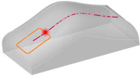
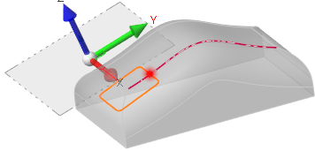
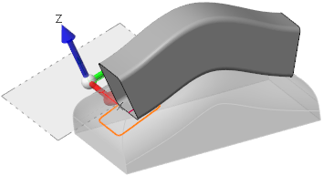
In the following example, the red surface edge was selected as the drive curve, the orange rectangle as the first and second shape with the same application point indicated by the red spot:
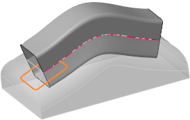
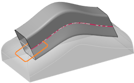
In the following example, the red surface edge was selected as the drive curve, the orange rectangle as the first and second shape with its centre points as the application points:
In the following example, the red surface edge was selected as the drive curve, the orange rectangle as the first and second shape with the same application point indicated by the red spot:
|
|
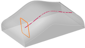
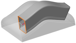
Surface sections |
Surface sections may be computed in three ways. Clicking on the For the examples, the red surface edge was selected as the drive curve, the orange rectangle as the first and second shape with the same application point indicated by the red spot:
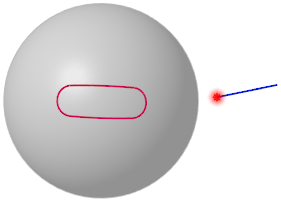
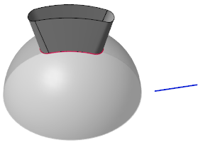
After having selected the drive and the shape curves, activate this option and then click the Section body option and select the reference body in the graphics area. In the following example, the red drive curve is selected along with the blue line and application point for the two shapes to create a surface normal to the grey body.
|
|
Section body |
This option becomes available if Shape curve normal to body is active in the Surface sections options. It allows you to select the required body. |
 symbol displays a list allowing you to select from the following options:
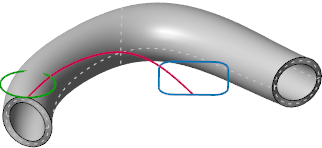
Advanced Options
This dialog box section allows you to define some additional characteristics of the surface to be created.
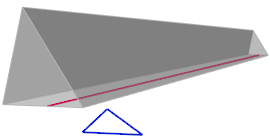
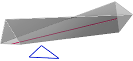
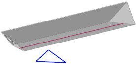
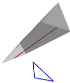
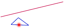
The following examples are based on the red guide curve and the blue triangle and application point for the two shapes:
|
Scales |
The Scale for the first shape curve and Scale for the second shape curve options allow you to apply a scale factor to the corresponding shape curves. Click the In the following example, the scale for the first shape curve was set to 2 and for the second shape curve to 0.5:
|
|
Rotate around drive curve |
Activate this option if you want to apply rotation angles to the start and end shape curves around the drive curve. Click the In the following example, a rotation angle of 90° was applied to the end shape curve:
|
|
Rotate along drive curve |
Activate this option if you want to apply rotation angles to the start and end shape curves along the drive curve. Click the In the following example, a start angle of -45° and an end angle of 45° were applied:
|
|
Rotate across drive curve |
Activate this option if you want to apply rotation angles to the start and end shape curves across the drive curve. Click the In the following example, a start angle of 70° was applied:
|