Offset a curve
![]()
This function allows you to create a curve offset at a given distance from a reference curve. You can create the offset on one or both sides of the reference curve.
Access
- Click the
 icon in the Wireframe tab.
Or
- Type "Offset curve" in the Quick Search field and then press Enter.
Procedure
- Select the curve.
- The Options - Offset dialog box is displayed:
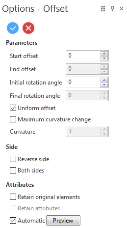
This dialog box allows you to apply a uniform offset, or a different offset at the start and end points of the curve. It also allows you to set offset values and rotation angles.
Uniform Offset
- Select the Uniform offset option.
- Define the Start offset:
- By dragging the Start offset arrow in the graphic area.
- By entering the value in the Start offset field in the graphic area or in the Options - Offset dialog box.
- Define the Initial rotation angle:
- By dragging the Initial rotation angle arrow in the graphic area.
- By entering the value in the Initial rotation angle field in the graphic area or in the Options - Offset dialog box.
- Validate, either by a Right Mouse click or by clicking the
 icon in the graphic area or in the function dialog box.
 - Reference curve
- Offset curve

|
|
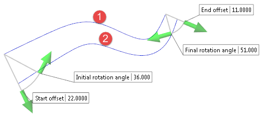
Different Offset at Start and End Points
- Deselect the Uniform offset option.
- Define the Start offset:
- By dragging the Start offset arrow in the graphic area.
- By entering the value in the Start offset field in the graphic area or in the Options - Offset dialog box.
- Define the End offset:
- By dragging the End offset arrow in the graphic area.
- By entering the value in the End offset field in the graphic area or in the Options - Offset dialog box.
- Define the Initial rotation angle:
- By dragging the Initial rotation angle arrow in the graphic area.
- By entering the value in the Initial rotation angle field in the graphic area or in the Options - Offset dialog box.
- Define the Final rotation angle:
- By dragging the Final rotation angle arrow in the graphic area.
- By entering the value in the Final rotation angle field in the graphic area or in the Options - Offset dialog box.
-
Validate, either by a Right Mouse click or by clicking the
icon in the graphic area or in the function dialog box. - Reference curve
- Offset curve
|
|
Initial/Final Rotation Angle
You can use these parameters to twist the offset curve through its length by defining a different rotation at the start to that at the end:
- The curve points are rotated through an angle with respect to the workplane.
- For a curve defined in the XY plane, applying a rotation angle of 90° to the offset curve will produce a constant offset in Z.
- Varying the rotation from 0° to 90° will produce a twisted curve which starts on the XY plane and gradually descends in Z.
Maximum Curvature Change
This option allows you to control the variation of the created curve.
- Select the Maximum curvature change option.
- Enter the Curvature value in the corresponding field.
The smaller the value is, the closer the resulting curve is to the reference curve.
Side
Selecting the Reverse side option allows you to create the offset on the other side of the reference curve.
Selecting the Both sides option allows you to create the offset on both sides of the reference curve.
Attributes
Selecting the Retain original elements option allows you to keep the reference curve after validating the function. It also makes the Retain attributes option available.
Selecting the Retain attributes options allows you to apply the attributes (colour, style) from the reference curve to the offset curve.
Preview
Preview generation is Automatic if this option is active. Otherwise, click on the Preview button to obtain a preview in the graphic area.
![]() Note: You can take measurements using the various options in the Measurement menu on the Options tab.
Note: You can take measurements using the various options in the Measurement menu on the Options tab.