Move Faces
![]()
The Move Faces function allows you to move, extrude or offset/reblend selected faces using several methods.
Access
- Click the
 icon in the Designer tab of the application.
 - Activate the Modelling tab and then click the icon in the Forms section of the ribbon.
- This option may also be available in the context menu accessed by a Right Mouse click.
In all cases, this opens the Move a face Options tab which is displayed along with the ribbon containing the Options, Filters and Selection sections.
Procedure
- Using the Face selection filters, select the face(s) which you want to move.
- Press the Right Mouse button to validate your selection and to display the Options - Move faces dialog box.
 See dialog box.
- Select the required option according to the result you want to obtain: Move, Extrude or Offset/Reblend.
Note that the slider display is different for the three options. - Set the options defining which faces or edges will be impacted by transformations to apply.
- Either by using the slider widget in the graphic area (change its position as required) or by directly entering the values in the Transformation fields, apply the required transformations.
The options in the Measurement menu section in the ribbon help you to define specific points. - Validate, either by a Right Mouse click or by clicking the
 icon in the graphic area or in the function dialog box.
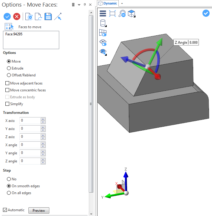
Move Faces Options
The following options are available in the Options - Move Faces dialog box:
Top Toolbar
![]()
![]()
![]()
![]()
![]()
![]()
![]()
![]()
![]()
From left to right, this toolbar displayed at the top of the option dialog box allows you to Apply the current values, to Cancel the current function, to Restore the system defaults and to Restore the defaults that have previously been saved using the Save icon.
Faces to Move
Clicking on the ![]() icon switches back into the element selection mode allowing you to modify your selection by selecting/unselecting elements in the graphic area.
icon switches back into the element selection mode allowing you to modify your selection by selecting/unselecting elements in the graphic area.
Use the ![]() icon (or Right Mouse click) to Validate your selection. The
icon (or Right Mouse click) to Validate your selection. The ![]() icon (or [Esc]) cancels the selection mode.
icon (or [Esc]) cancels the selection mode.
Select a Direction
By default, the direction for function application is defined by the system and coincides with the normal orientation of the selected face(s). The Select a direction ![]() icon allows you to define another direction.
icon allows you to define another direction.
- Click on the icon to activate the function and to display the normal vector arrows on the previously selected faces.
- Click on the required vector to define it as direction. A second, longer direction arrow is added. See illustration.
You may use the Space Bar to reverse the direction.
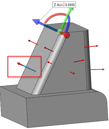
- Right click to validate the direction.
You may also use the Direction definition options that become available on the ribbon at function selection.
Options section
|
Move |
Activate this option to move the selected items. |
|
Extrude |
Activate this option to extrude the selected items. |
|
Offset/Reblend |
Activate this option to apply an offset to the selected faces or to change the radius value of concentric faces such as blends or cylinders. |
|
Move adjacent faces |
This option is available when either Move or the Offset/Reblend operation is selected. If it is active, it moves all the adjacent faces along with the selected elements. |
|
Move concentric faces |
This option is available when either Move or the Offset/Reblend operation is selected. When moving circular items and this option is active, it simultaneously moves concentric faces. |
|
Extrude as body |
This option is available when the Extrude operation is selected. It allows you to extrude the selected items as a body. |
|
Simplify |
Activate this option to remove all of the unnecessary lines created by the applied transformations. |
The Transformation section allows you to enter or adjust the X, Y and Z axis and angle transformation values. They are automatically updated according to the slider movements in the graphic area.
The Step section allows you to select an option from No, On smooth edges and On all edges. This section is not available with the Extrude option.
Preview
Preview generation is Automatic if this option is active. Otherwise, click on the Preview button to obtain a preview in the graphic area.
See also...