Blend Options - Advanced Tab
The following options are available in the Advanced tab of the Options - Blends dialog box:
Top Toolbar
![]()
![]()
![]()
![]()
![]()
![]()
![]()
![]()
![]()
From left to right, this toolbar displayed at the top of the option dialog box allows you to Apply the current values, to Cancel the current function, to Restore the system defaults and to Restore the defaults that have previously been saved using the Save icon.
Options
| Create sheet on failure |
If this option is active and the blends cannot be performed on a selected edge, a sheet entity is created.
|
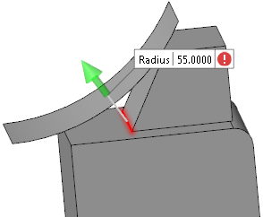
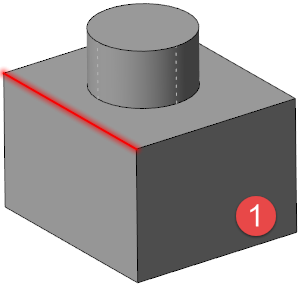
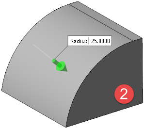
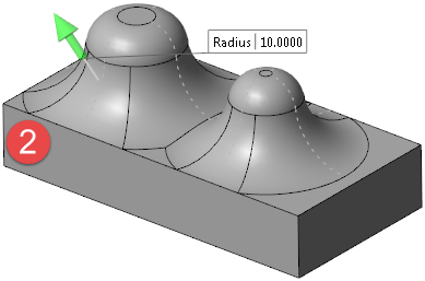
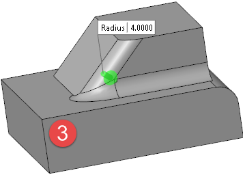
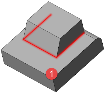
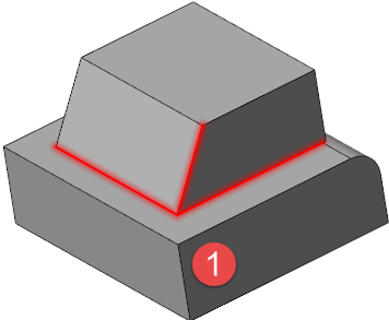
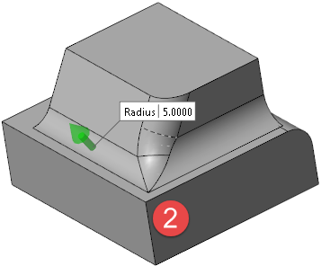
| Local validate | This option works together with the Repair option. It verifies whether the region in which the blend is to be created is still valid. If it is not valid, it blocks the blend creation which is the case for the selected edge  with the radius specified in with the radius specified in  in the following illustration. in the following illustration. |
|
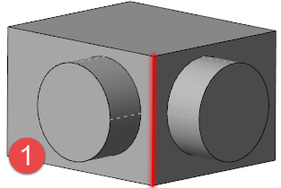
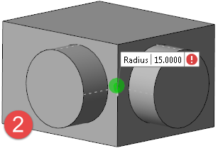
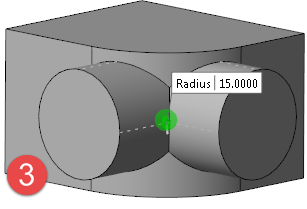
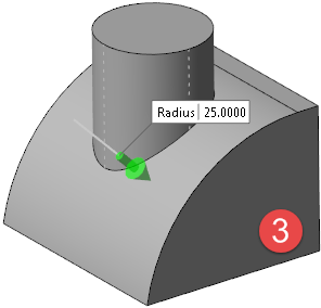
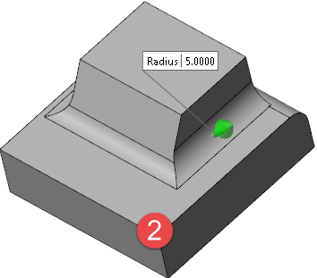
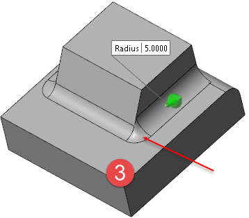
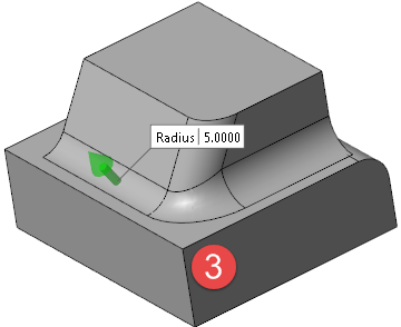
Repair |
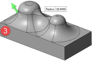
This option works together with the Local validate option. If it is active and the Local validate option invalidated the blend creation, it tries to automatically fix the issue and, if successful, creates the blend as shown in |
|
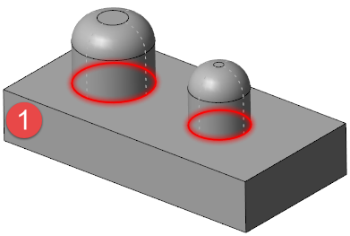
Retain geometry |
This option can be used when a blend completely overlaps a feature. It allows you to decide whether to retain that feature (option active - |
|
Tolerance |
This field is available when the Blend type in the General tab is set to Variable radius blend and the Use default tolerance option is not active. It allows you to set another tolerance. |
|
Use default tolerance |
Activate this option to apply the default tolerance to variable blend creation. |
Methods
|
Smooth overlapping |
This option defines how overlapping blend faces are handled. In the following illustration, |
|
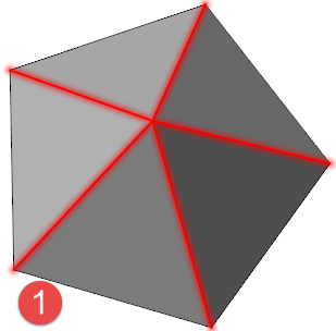
Y shaped |
This option defines how blending is handled on y-shaped edges. In the following illustration, shows the selected edges, shows the result when this option is active and  when it is inactive. when it is inactive. |
|
Blend at vertex |
This option defines whether the blend is applied to vertexes or not. In the following illustration, shows the selected edges, shows the result when this option is not active and when it is active. |
|
Convex blended first |
This option allows you to define the blending order. If this option is active, the convex edges are blended first. In the following illustration, shows the selected edges, shows the result when this option is not active and when it is active. |
Set Back
The options in this section are available if there is at least 3-edge vertex where the blend is to be applied.
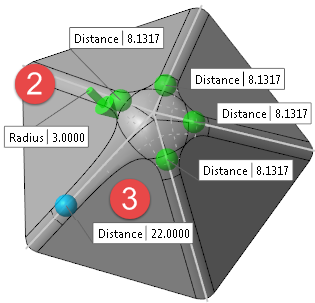
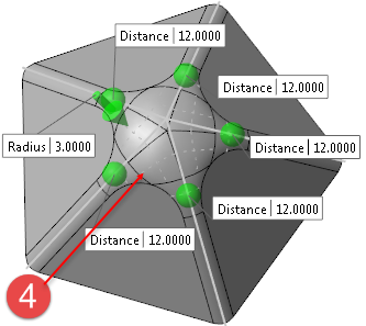
| Set back |
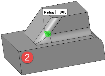
This option allows you to individually define the blend distances with respect to the intersection point of the selected edges and to directly modify the applied radius ( To apply a new distance, drag the relevant Distance sphere ( |
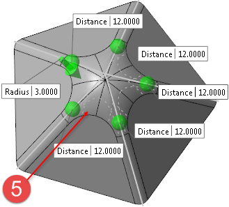
| Collar faces | This option determines how the blend faces are handled at the intersection point. The following illustration shows this option active  and inactive and inactive  . . |
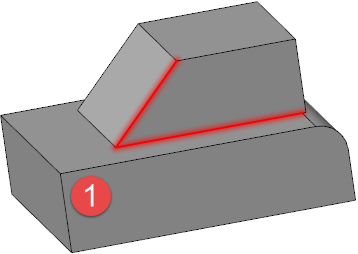
The following example shows the result for the selected edges :
Preview
Preview generation is Automatic if this option is active. Otherwise, click on the Preview button to obtain a preview in the graphic area.
See also...