Workplanes - Overview
A workplane is the graphical equivalent of a sheet of paper. When a 2D element is created, it will be placed on this sheet of paper which is, in fact, the XY plane of the current workplane.
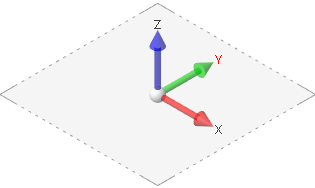
The plane's origin and orientation are shown in the graphic area by the three labelled X, Y and Z axes. These axes represent three mutually perpendicular planes whose point of intersection is the origin of the workplane.
The relative positions of those axes are defined by the right hand rule (Z equivalent to the thumb, X the first finger and Y the second). A visible dotted line rectangular border gives the general idea of where the workplane is lying.
When the application is started there is only one workplane. This is the Absolute plane where the X, Y and Z axes are parallel to the world axis system and the origin is at X0, Y0, and Z0. The Absolute workplane always exists and cannot be deleted, edited or modified.
There are numerous ways to create and edit other workplanes. Each newly created workplane is automatically saved with a default name.
You may switch between the standard planes (XY Top = top view, XZ Front = front view or YZ Side = side view) by a Left Mouse click on the Workplane entry in the Message/Status bar at the bottom of the user interface:
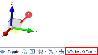
As an alternative, you may also click on the required plane representation of the trihedron displayed in the lower left corner of the graphic area as shown in  .
.
For further information...