Blends
![]()
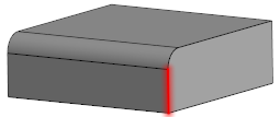
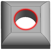
The Blend function creates a constant or variable radius blend (or fillet) between the faces of a solid forming an edge. You can add blends to all edges of a face, selected sets of faces, selected edges or edge loops.
Access
- Click the
 icon in the Solids section of the Designer tab.
 - Activate the Solids tab and then click the icon in the Operations section of the ribbon.
- Type Blend in the Quick Search field and select Blends from the result list.
In all cases, this opens the Blends - Options tab which is displayed along with the ribbon containing the Filters and Selection sections and the Options - Blends dialog box. ![]() See dialog box.
See dialog box.
Procedure
In the following steps, confirmation by Right Mouse click may be required if Multi-select ![]() is active in the Selection options.
is active in the Selection options.
- Using the Edge selection filters, select the edge(s) which you want to blend.
- Select the required options according to the result that you want to achieve.
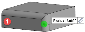
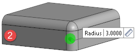
- Using the Radius slider, its value input box or the Radius field in the dialog box, define the blend radius to apply.
- Validate, either by a Right Mouse click or by clicking the
 icon in the dialog box.
Clicking on the Measurement ![]() icon on the slider label displays the Measurement Menu which helps you to define specific points.
icon on the slider label displays the Measurement Menu which helps you to define specific points.
![]() Note: If mandatory values are missing or if erroneous values are entered, an exclamation mark
Note: If mandatory values are missing or if erroneous values are entered, an exclamation mark ![]() is displayed in the relevant slider value input box and the background of the corresponding parameter input box in the Options panel is displayed in red.
is displayed in the relevant slider value input box and the background of the corresponding parameter input box in the Options panel is displayed in red.
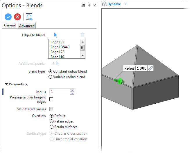
Blend Options - General Tab
The following options are available in the General tab of the Options - Blends dialog box:
Top Toolbar
![]()
![]()
![]()
These two icons at the top of the dialog box allow you to Apply the current values or to Cancel the current function.
Preview generation is Automatic if this option is active in the dialog box menu accessed by clicking on the  icon. If this option is not active, click on the
  icon. If preview generation is not possible, the icon is greyed out.
Edges to blend
The Edges to blend field lists the identifiers of the selected edges.
Clicking on the ![]() icon switches back into the selection mode allowing you to modify your selection by selecting/unselecting elements in the graphic area. Use the
icon switches back into the selection mode allowing you to modify your selection by selecting/unselecting elements in the graphic area. Use the ![]() icon (or Right Mouse click) to Validate your selection. The
icon (or Right Mouse click) to Validate your selection. The ![]() icon (or [Esc]) cancels the selection mode. If you want to delete elements within your selection, select the required elements and then click the
icon (or [Esc]) cancels the selection mode. If you want to delete elements within your selection, select the required elements and then click the ![]() icon above the list field. You may use the [Ctrl] + [A] shortcut to select all of the elements.
icon above the list field. You may use the [Ctrl] + [A] shortcut to select all of the elements.
Additional Points
Blend Type
|
Constant radius blend |
Select this option to apply the same radius to all of the previously selected edges. |
|
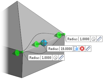
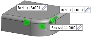
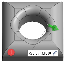
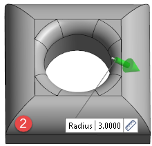
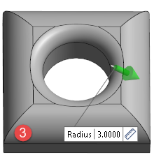
Variable radius blend |
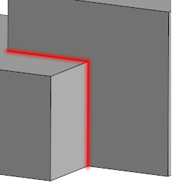
Select this option to apply different radius values to the selected edges. In this case, a Radius slider is displayed in the graphic area on all of the selected edges allowing you to enter individual values for each edge. The radius initially proposed is the one entered in the Radius field in the Parameters section of the dialog box. Using the The following illustration shows a variable radius blend for the selected red edges:
|
![]() Note:
Note:
When the Variable radius blend option is active, the slider labels in the graphic area display additional icons:
- You may use the
 icon to restore the value entered in the Radius field in the Parameters section of the dialog box.
 - Click
 to cancel and close the radius input box for the corresponding location. In this case, the radius entered in the Parameters section of the dialog box will be applied.
Parameters
|
Radius |
Use this input field to enter the radius to be applied for blending. |
|
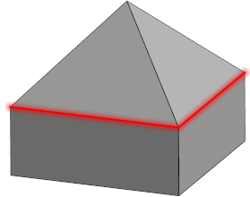
Propagate over tangent edges |
Activate this option to propagate blend creation over tangent edges. In the following example, for the selected red edge, this option is not active in
|
|
Set different values |
This option is available when the Constant radius blend option is selected as the Blend type. It is similar to variable radius blend but displays a simple radius value input box and does not allow you to create additional points.
|
 and active in
  .
.
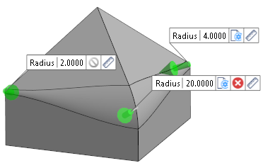
Overflow
This option defines how faces are handled when the newly created blends overlap existing faces. This is shown in the examples below for the selected red edge with respect to the existing blends.
|
Default |
Selecting this option applies the defaults from the CAD engine ( |
|
Retain edges |
Activate this option if you want to retain the edges of the created blend and any adjacent faces ( |
|
Retain surfaces |
Activate this option if you want to retain the newly created blend as a surface ( |
 in the illustration below).
Surface Type
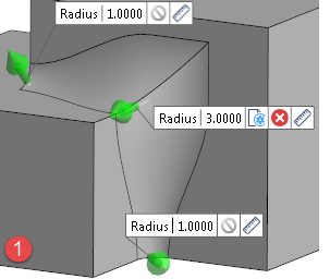
If Variable radius blend is active in the Blend type section, the following options are available:
|
Circular cross section |
Selecting this option creates a rounded blend ( |
|
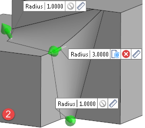
Linear radial variation |
Selecting this option creates a straight blend ( |
The following example shows the result for the selected red edges:
Information Field
The field at the bottom of the Options panel displays information about missing data, errors or actions.
For further information...