Chamfer
![]()
This function allows you to create chamfers at the vertices of two lines, at the angles of polygons, between two unconnected lines, etc.
 Hint: Use the Filters toolbox to determine the type of elements that can be selected before creating a chamfer.
Access
- Click on the
 icon in the Wireframe tab.
Or
- Type "Chamfer" in the Quick Search field and then press Enter.
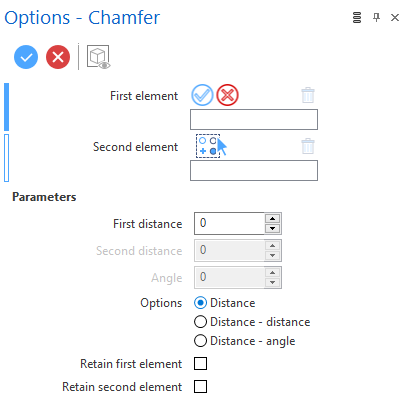
In both cases, the Options - Chamfer dialog box is displayed:
Procedure
Creating a Chamfer from 2 Distant Segments

- Select the first element.
- Select the second element.
- Select the chamfer creation option.
- Depending on the creation option selected, specify the distance(s) and/or angle:
- By dragging the green arrow in the graphic area.
- By entering the corresponding value in the distance and/or angle fields in the graphic area or in the dialog box.
- By clicking on the Measurement
 icon, in the graphic area or in the dialog box (next to the active field), and taking measurements.
 -
Validate, either by a Right Mouse click or by clicking the
 icon in the dialog box.
Creating a Fillet between 2 Joint Segments
- Click at the junction between the two segments.
- Select the chamfer creation option.
- Depending on the creation option selected, specify the distance(s) and/or angle:
- By dragging the green arrow in the graphic area.
- By entering the corresponding value in the distance and/or angle fields in the graphic area or in the dialog box.
- By clicking on the Measurement icon, in the graphic area or in the dialog box (next to the active field), and taking measurements.
-
Validate, either by a Right Mouse click or by clicking the
icon in the dialog box.
Parameters
The different Parameter fields are active or not depending on the selected Option.
Options
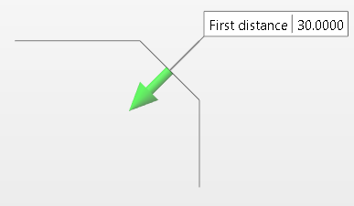
| Distance | Works as described in the example shown above. The First distance value can be modified in the corresponding field in the dialog box, in the corresponding field in the Graphic Area or by dragging the green arrow (turns blue) located on the chamfer in the Graphic Area. |
|
Distance - distance |
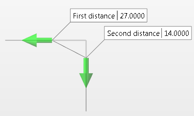
Selecting this option once the Options dialog box is displayed changes the chamfer definition mode. The First distance and Second distance value fields are both activated in the dialog box and are also available in the Graphic Area.
You can define the First and Second distance values using the input fields in the Graphic Area or the dialog box. Alternatively, you can press the left mouse button on either of the two arrows and drag in either direction. The value changes dynamically in the corresponding field. |
|
|
|
|
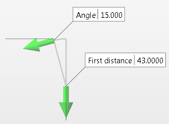
Distance - angle |
Selecting this option enables the First distance and Angle input fields in the dialog box and in the Graphic Area.
Alternatively, you can dynamically modify these values by pressing the left mouse button on either of the two arrows and dragging in either direction. |
|
|
|
|
Retain first/second element |
After validation, sections of the first and/or second elements that would normally be clipped and removed are retained as shown below:
|
![]() Note:
Note:
- Use the Attributes toolbox to modify the created entities.
Top Toolbar
![]()
![]()
![]()
These two icons at the top of the dialog box allow you to Apply the current values or to Cancel the current function.
Preview generation is Automatic if this option is active in the dialog box menu accessed by clicking on the  icon. If this option is not active, click on the
 ![]() icon. If preview generation is not possible, the icon is greyed out.
icon. If preview generation is not possible, the icon is greyed out.