2D Drawing - Section
![]()
You can create fixed and/or variable sections, as well as sections by profiles.
Creating a Fixed Section
- Select Fixed section from the Section drop-down list in the dialog box.
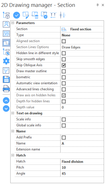
- Define the parameters in the dialog box.
- Click the
 icon at the top of the dialog box.
 - Select a view in the graphic area.
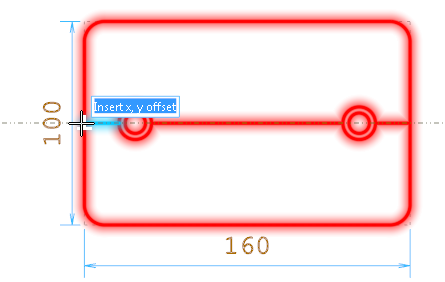
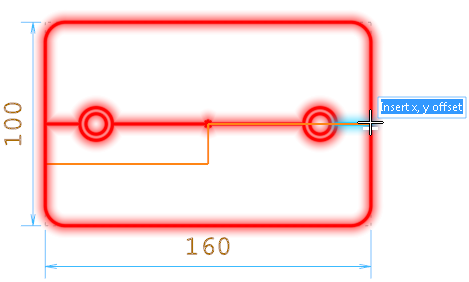
- Using the appropriate Filters, select a point to insert the planar section.
- Select the section line angle.
- Select the section direction: press the Space bar to invert the direction.
- Right click to validate.
- Click a point in the graphic area to insert the section view.
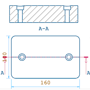
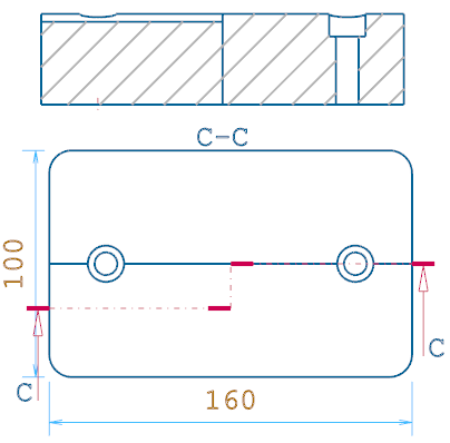
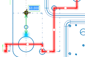
In the example below, the planar is inserted on a top view of a model with two though holes:
Result:
Creating a Variable Section
- Select Variable section from the Section drop-down list in the dialog box.
- Define the parameters in the dialog box.
- Click the icon at the top of the dialog box.
- Select a view in the graphic area.
- Using the appropriate Filters, select the first point of the section.
- Select the other points of the section. Note that you can undo your selection by clicking the
 Undo option in the ribbon.
 - Click the Confirm option in the ribbon or right click in the graphic area to validate the section.
- Select the section direction: press the Space bar to invert the direction.
- Right click to validate.
- Click a point in the graphic area to insert the section view.
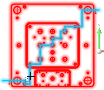
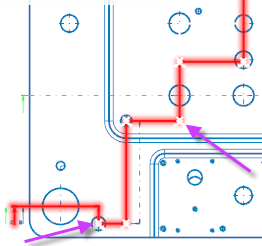
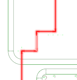
Picking points for variable section:
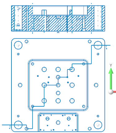
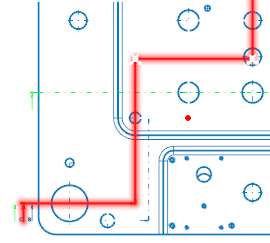
Result:
Creating a Section by Profile
- Select Section by profile from the Section drop-down list in the dialog box.
- Define the parameters in the dialog box.
- Click the icon at the top of the dialog box.
- Select a profile.
- Select the section direction: press the Space bar to invert the direction.
- Right click to validate.
- Click a point in the graphic area to insert the section view.
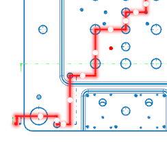
Picking a profile:
Result:
Editing Section Line
Modifying a Section Line (fixed, variable or by profile)
- Click the
 icon at the top of the dialog box.
 - Select the section line (fixed) or section line portion (variable or by profile).
- Control points are displayed on the selected section line.
- Click on the control point corresponding to the portion you want to move.
- Define new control point position.
-
Validate, either by a Right Mouse click or by clicking the
 icon in the graphic area.
 - The corresponding section view is updated accordingly.
|
Control points |
Defining new control point position: |
|
|
|
Deleting Portions of a Section Line (variable or by section)
- Click the
 icon at the top of the dialog box.
 - Select the section line portion (variable or by profile).
- Control points are displayed at each junction between the portions of the selected section line.
- Click on the control point(s) that you wan to delete.
-
Validate, either by a Right Mouse click or by clicking the
icon in the graphic area. - The corresponding section view is updated accordingly.
|
Control points to delete: |
Result: |
|
|
|
Adding Points to a Section Line (variable or by section)
- Click the
 icon at the top of the dialog box.
 - Select the section line portion (variable or by profile).
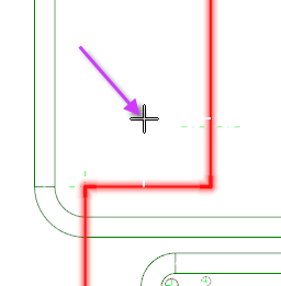
- Select the new point position.
- The corresponding section view is updated accordingly.
|
Adding a point |
Result: |
|
|
|
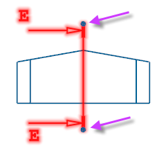
Moving Arrows (fixed section)
You can extend/reduce the section line dimension. The size of the section line must be at least equal to the size of the sectioned element:
- Click the
 icon at the top of the dialog box.
 - Select the section line to modify.
- Control points are displayed at each extremity of the section line.
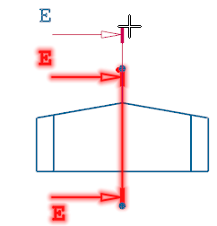
- Select the section line point to modify.
- Select the new point position.
-
Validate, either by a Right Mouse click or by clicking the
icon in the graphic area.
|
Section line control points |
Dragging a control point: |
|
|
|
Reversing the Section Line Direction
This option is available for all types of section line.
- Click the
 icon at the top of the dialog box.
 - Select the corresponding section line.
- The corresponding section view is updated accordingly.
Configuration
Parameters
|
Section |
|
|
Type |
|
|
Aligned section |
This option is available when the Variable section or Section by profile is enabled. It is useful when there are inclined segments in the section. Activate this option to project the inclined portion along the section direction. |
|
Section Lines Options |
This drop-down list is available when the Variable section or Section by profile is enabled. It allows you to represent the direction changes in different modes:
|
|
Hidden line in different style |
Each view shows the lines that are not visible as dotted lines. Activate this option to create views without lines that are not visible. |
|
Skip smooth edges |
Smooth edges are, for example, edges of a blend with the adjacent faces (tangent edges). Activate this option if you do not want smooth edges to be represented on the created views. |
|
Skip Oblique Axis |
Activate this option to create views without the axis of the holes that are NOT perpendicular to the direction of the view/section. |
|
Draw master outline |
Activate this option to display the elements on a section line in a different colour (default is purple ). |
|
Isometric |
Activate this option to obtain a sectioned isometric draw of the selected view. |
|
Automatic view orientation |
Activate this option to automatically align the newly created view/section to the reference view. |
|
Advanced lines checking |
Activate this option to improve the quality of the view/section to be generated. As this option uses a different function for the calculation of hidden lines, the time needed to view the final result will be longer. You can activate it if your model has intersecting bodies, meaning that the hidden line calculation will need to be more advanced. |
|
Draw axis on hidden holes |
This option is available when the Hidden line in different style option is enabled. Activate this option to draw axes on hidden holes. |
|
Depth for hidden lines |
This option is available when the Hidden line in different style option is enabled. Activate this option to enable the Depth value field for the hidden lines representation. |
|
Depth value |
Enter the depth value for the hidden lines representation. This allows you to represent the hidden lines of the part only for that depth value and the lines that are outside of this value will be ignored. In this way, the representation of the part with hidden lines will be clearer. |
Text on drawing
These options allow you to place the text with the scale information on views, sections and details:
|
Scale info |
Text information relating to the scale of the view/section/detail. |
|
Global scale info |
Scale of the view/section/detail according to its scale and the global scale. |
Example:
For a view with scale = 0.5 and placed in a page with Global Scale = 0.4, the text info will be:
- Scale info: 1:2
- Global scale (plotting) info: 1:5
The Scale applied to the view/section/detail will be automatically considered by the system when dimensioning elements belonging to the detail.
Name
|
Add Prefix |
Activate this option to add the "Sect." prefix to the name of the section. |
|
Name |
Enter the name of the section in this field. This name is automatically incremented when creating a new section (e.g. Sect. A-A, Sect. B-B, Sect. C-C). |
|
Extension name |
Enter comments about the section in this field. |
Hatch
|
Hatch |
This drop-down list allows you to define the hatching representation mode:
|
|
Pitch |
This field is available when the Fixed division option is enabled. Enter the pitch value in this field. |
|
Angle |
Enter the inclination angle for the hatching in this field. |
2D Drawing Tab
This tab of the ribbon contains the following icons:
|
|
Click this icon to update a selected view/section with new parameters. |
|
|
Click this icon to update all views/sections with new parameters. |
|
|
Click this icon to access the View Properties dialog box. |
|
|
Click this icon to access the Page Properties dialog box. |
For further information...