2D Drawing - Electrode
![]()
This tab allows you to create pages with views for electrodes.
- Select the electrodes for which you want to create pages in the Electrode list tab.
- Define the parameters in the Electrode views and Layout views tab.
- Click the
 icon at the top of the dialog box.
 - A page is created for each electrode in the General tab of the 2D Drawing Manager.
Electrode Views Tab
This tab allows you to configure the views of the electrode(s) only.
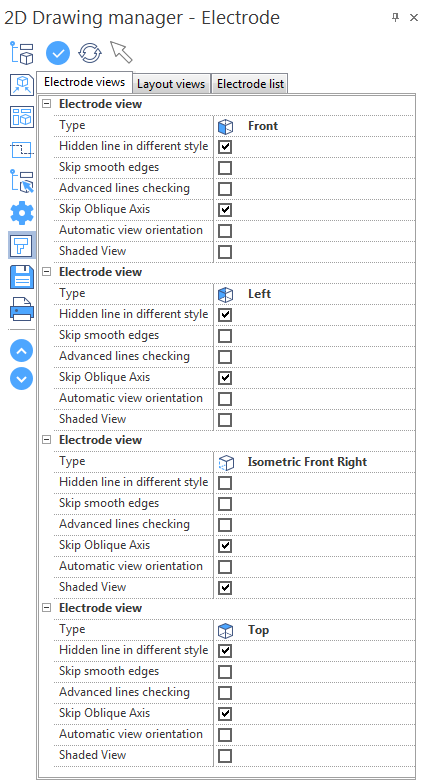
Configuration
|
Type |
|
|
Hidden line in different styles |
Each view shows the lines that are not visible as dotted lines. Activate this option to create views without lines that are not visible. |
|
Skip smooth edges |
Smooth edges are, for example, edges of a blend with the adjacent faces (tangent edges). Activate this option if you do not want smooth edges to be represented on the created views. |
|
Advanced line checking |
Activate this option to improve the quality of the view/section to be generated. As this option uses a different function for the calculation of hidden lines, the time needed to view the final result will be longer. You can activate it if your model has intersecting bodies, meaning that the hidden line calculation will need to be more advanced. |
|
Skip oblique axis |
Activate this option to create views without the axis of the holes that are NOT perpendicular to the direction of the view/section. |
|
Automatic view orientation |
Activate this option to automatically align the newly created view/section to the reference view. |
|
Shaded view |
Activate this option to create a shaded view. When this option is deactivated, the view has a wireframe representation. |
Layout Views
This tab allows you to configure the views of the electrode and the CAD model.
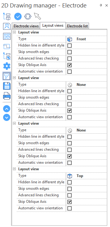
- See Electrode Views for details of the parameters.
Electrode List
This tab allows you to select the electrodes for which you want to create pages.
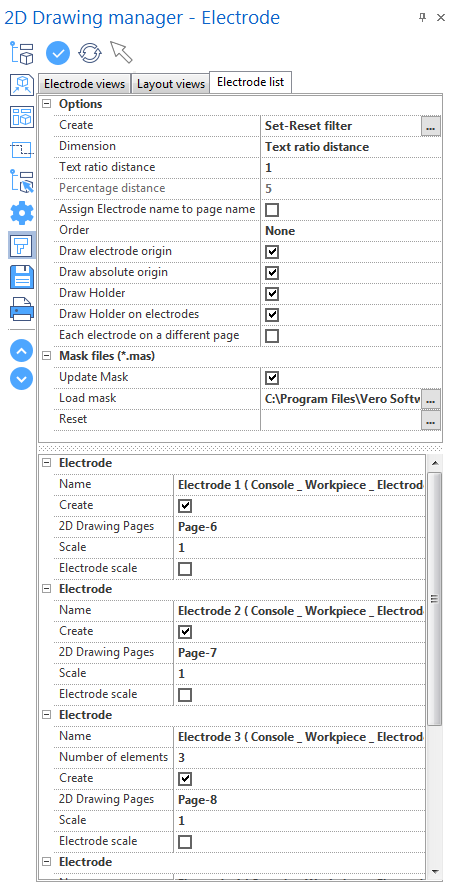
Options
|
Create |
Click the [...] icon to set or reset the parameters in the electrode list. |
|
Dimension |
This parameter allows you to select the way to calculate the distance between dimensions and electrode views:
|
|
Text ratio distance |
Enter the ratio factor to be used to calculate the distance between dimensions and views if the Dimension option is set to Text ratio distance. |
|
Percentage distance |
Enter the percentage to be used to calculate the distance between dimensions and views if the Dimension option is set to Percentage distance. |
|
Assign Electrode name to page name |
Activate this option to apply the electrode name to the corresponding page name. |
|
Order |
From the drop-down menu select the required ordering mode. Double-click on the input field to display the options. |
|
Draw Electrode Origin |
Activate this option to display the electrode origin in the 2D Drawing. |
|
Draw Absolute Origin |
Activate this option to display the electrode absolute origin when the view is generated with respect to a relative one. |
|
Draw Holder |
Activate this option to display the electrode holder in the 2D Drawing. |
|
Draw Holder on electrodes |
Activate this option to display the electrode origin in the 2D Drawing. |
|
Each electrode on a different page |
Activate this option to display multiple electrodes on different pages. |
Mask Files
|
Update Mask |
Activate this option to allow the mask update. |
|
Load mask |
|
|
Reset |
Click the [...] icon to reset the mask. |
Electrode List
|
Name |
This field displays the name of the corresponding electrode. |
|
Create |
Activate this option to create the corresponding electrode page on the 2D Drawing. |
|
2D drawing pages |
|
|
Scale |
Enter the scale factor in this field. |
|
Electrode scale |
Activate this option to apply the electrode scale. |
For further information...