Import Interfaces - Pro-ENGINEER and NX Unigraphics - Options
Designer can import and handle assemblies from other systems. This means it can manage solids, groups of solids, wireframe, attributes and part list data from Unigraphics and Pro-ENGINEER libraries.
![]() Note:
Note:
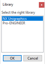
- As both libraries use the *.prt extension, when importing a ".prt" file, you will be prompted to select either NX Unigraphics or Pro-ENGINEER (
 see image).
 - The layers in Designer start with index 0 but Unigraphics layers start with index 1. Therefore, Layer X in Unigraphics is mapped to Layer X-1 in Designer.
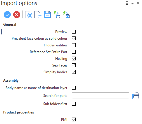
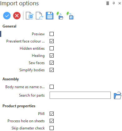
Import options Dialog Box for NX Unigraphics and Pro-ENGINEER
The content of the imported file is managed using the configuration options available in the Import options dialogs for ![]() NX Unigraphics and
NX Unigraphics and ![]() Pro-ENGINEER.
Pro-ENGINEER.
Top Toolbar
![]()
![]()
![]()
These two icons at the top of the dialog box allow you to Apply the current values or to Cancel the current function.
|
Restore system defaults
|
Clicking this icon restores the system default settings. Any other settings are lost. |
|
Restore defaults
|
Clicking this icon allows you to restore the user default settings previously saved by using the Save defaults icon. |
|
Save defaults
|
Clicking this icon allows you to save the current settings as user default settings. |
|
Load parameters from file
|
Clicking this icon allows you to load the required settings from a *.snp file previously saved by using the Save parameters to file icon. |
|
Save parameters to file
|
Clicking this icon allows you to save the current settings into a *.snp file. This option is very useful when you need to define multiple settings for regular use according to your needs. |
|
General |
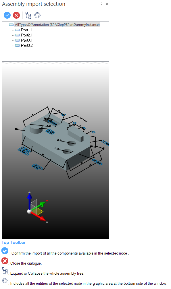
Define how the system manages the different entities when importing models from NX Unigraphics and Pro-ENGINEER. Preview: Activate this option to display, after confirming the Import options dialog, a further dialog named Assembly import selection. This dialog allows you to control what has to be imported into Designer by selecting only the required components from the assembly. ( The file content is displayed at the bottom of the window and it is possible to interact with it (zoom, rotate, translate).
Prevalent face colour as solid colour: When selected, the system associates the colour common to the majority of its faces with the solid body. For example, if, in the native software, 2 faces are red and 5 are blue, the imported solid will be blue. Hidden entities: When selected, the system imports the entities which have an associated invisible attribute. Healing: The default healing workflow performs multiple checks and, based on the results, activates specific procedures in order to fix the detected errors. This could result in re-surfacing of faces, faces being split, bodies being split etc. The Healing option performs the following operations when activated:
Sew faces: Activate this option to sew all faces to be imported. Otherwise, the model is imported with single faces.
In general, this option is activated for stitching trimmed faces (trim route). Simplify bodies: Activate this option to attempt to simplify bodies by:
Reference Set Entire Part: This option controls the Entire Part Reference Set while importing an NX Unigraphics assembly. The Entire Part Reference Set is a standard configuration created by Unigraphics itself and available in all of the Unigraphics files. Activate this option to set the ConfigName 'Entire Part' as Reference Set. The contents of the Entire Part Reference Set will be used to reference / define each assembly in Designer. |
|
Assembly |
This section allows you to handle the assemblies imported from systems other than Designer by defining how to manage the different entities. Body name as name of destination layer: By activating this option, the layer where the imported body is placed inherits the name of the body in the native system. Search for parts: Enter the path to be used to search for the components and the sub-assembly files to load.
C:\Temp\PartFiles, C:\Temp, C:\, E:\Files\MissingParts, E:\Files, and E:\. Sub folders first: This option controls the relative and absolute paths searched for parts and sub-assembly files while importing a NX Unigraphics assembly. Activate this option to first check for sub-assemblies and parts at the root folder of the assembly. If any sub-assembly or part is not found in the root folder, it checks for sub-assemblies and parts in an equivalent relative sub-folder to the root assembly folder.
When the Searches for parts and Sub folders first options are both applicable for a component (because of default behaviour or explicitly set), Searches for parts will be performed first. If any file is not successfully found in the specified path, then Sub folders first will be used. |
|
Product Properties |
These options are used to manage the part list attributes imported. PMI: By selecting this option, the Product Manufacturing Information (PMI) attached to the design of product components for manufacturing can be imported Process hole on sheets: Activate this option to import the hole's attributes.
Skip diameter check: In some specific situations, related to the method of modelling used in Pro-ENGINEER, the system itself shows planar faces as owners of the hole attributes. In this case, Designer creates cylindrical sheets close to the real holes, to which the relevant CAM attributes are attached. These attributes can then be assigned to the proper holes removing the additional sheets. |
Further information on Import