Import Interfaces - IGES and CATIA - Options
Designer can import geometry and annotations from IGES and CATIA files.
![]() Note:
Note:
The IGES specification is comprehensive and different vendors implement it in a multitude of different ways. When the default All supported files is selected in the Load a file dialog and an IGES file is selected, the ![]() IGES Library dialog is displayed. You can choose between IGES and IGES containing PMIs. Direct selection of an IGES or IGES PMI file in the file type list eliminates this step.
IGES Library dialog is displayed. You can choose between IGES and IGES containing PMIs. Direct selection of an IGES or IGES PMI file in the file type list eliminates this step.
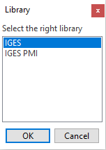
- CAD users are allowed to add semantic Product Manufacturing Information (PMI) to their projects. The system itself will then generate the graphical representation of it (graphical PMI) in order to show it on the screen.
- As there is no direct correspondence between the different systems for these entities, the conversion will generate 2D groups. When selecting the IGES PMI library to import this type of data, the Import options Dialog Box for IGES PMI Library is displayed.
Import options Dialog Box for CATIA and IGES
The content of the imported file is managed using the configuration options available in the Import options dialogs for ![]() CATIA or
CATIA or ![]() IGES.
IGES.
Top Toolbar
![]()
![]()
![]()
These two icons at the top of the dialog box allow you to Apply the current values or to Cancel the current function.
|
Restore system defaults
|
Clicking this icon restores the system default settings. Any other settings are lost. |
|
Restore defaults
|
Clicking this icon allows you to restore the user default settings previously saved by using the Save defaults icon. |
|
Save defaults
|
Clicking this icon allows you to save the current settings as user default settings. |
|
Load parameters from file
|
Clicking this icon allows you to load the required settings from a *.snp file previously saved by using the Save parameters to file icon. |
|
Save parameters to file
|
Clicking this icon allows you to save the current settings into a *.snp file. This option is very useful when you need to define multiple settings for regular use according to your needs. |
|
General |
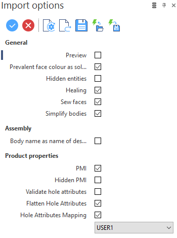
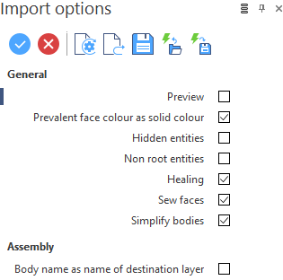
Define how the system manages the different entities when importing models from IGES and CATIA.
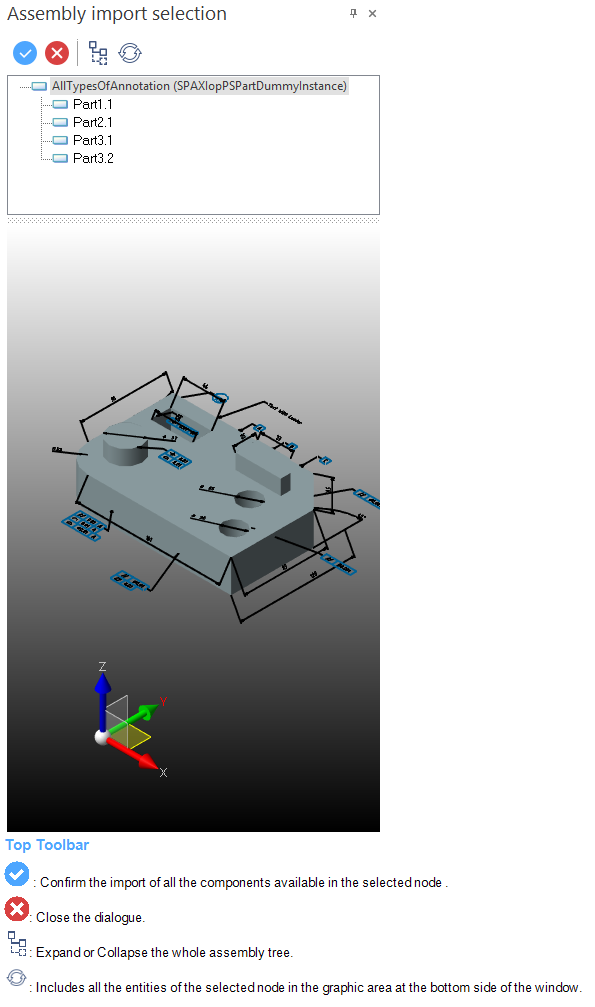
Workplanes, which are simple planes used as reference geometries during the modelling, exist in most of the major CAD applications. The system reads this information from CATIA and translates the workplanes as sheet bodies. Preview: Activate this option to display, after confirming the Import options dialog, a further dialog named Assembly import selection. This dialog allows you to control what has to be imported into Designer by selecting only the required components from the assembly. ( The file content is displayed at the bottom of the window and it is possible to interact with it (zoom, rotate, translate).
Prevalent face colour as solid colour: When selected, the system associates the colour common to the majority of its faces with the solid body. For example, if, in the native software, 2 faces are red and 5 are blue, the imported solid will be blue. Hidden entities: When selected, the system imports the entities which have an associated invisible attribute. Healing: The default healing workflow performs multiple checks and, based on the results, activates specific procedures in order to fix the detected errors. This could result in re-surfacing of faces, faces being split, bodies being split etc. The Healing option performs the following operations when activated:
Sew faces: Activate this option to sew all faces to be imported. Otherwise, the model is imported with single faces.
In general, this option is activated for stitching trimmed faces (trim route). Simplify bodies: Activate this option to attempt to simplify bodies by:
Non root entities (IGES only): The entities in a file are managed in the form of an hierarchy from which the translator determines a set of entities classified as root entities. Select this option to import all entities and not just the root entities.
|
|
Assembly |
This section allows you to handle the assemblies imported from systems other than Designer by defining how to manage the different entities. Body name as name of destination layer: By activating this option, the layer where the imported body is placed inherits the name of the body in the native system. |
|
Product properties |
This section allows you to accommodate the part list attributes coming from the imported files. PMI: By selecting this option the Product Manufacturing Information (PMI) attached to the design of product components for manufacturing can be imported. Hidden PMI: By selecting this option, all PMI available in the source file will be imported regardless of the visibility attribute.
Validate Hole Attributes: In some cases, probably due to the modelling procedure, the values of the Drill and Tap Depth could be incorrect. The problem can be resolved by checking this option which then runs the Holes functionality. Flatten Hole Attributes: This option allows you to retain the attributes of the imported holes when, in the native software, they have been created using a schema of negative solids or as portion of a sub-schema. (Example of a schema: plate with 15 holes resulting from a pattern of 5 horizontal holes X a pattern of 3 vertical holes).
Hole Attributes Mapping: To provide the CAM information relating to the defined standards for files imported from a CATIA V5 model, each CAM attribute read from this system can be mapped to the relevant Holes type (e.g. DRILL_3) and relevant colour (e.g. DRILL_3 = 43):
|
Import options Dialog Box for IGES PMI Library
When selecting the IGES PMILibrary, the system displays the ![]() IGES Import options dialog which allows you to modify the format and content of the imported file using the configuration options available on the General, Geometry, Trimming and Advanced tabs:
IGES Import options dialog which allows you to modify the format and content of the imported file using the configuration options available on the General, Geometry, Trimming and Advanced tabs:
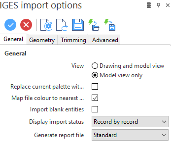
General options ( see dialog)
|
General |
View: IGES files can contain both model views and drawing views. The drawing views are similar to the 2D drawing pages. This option allows you to define the type of view to import into Designer. Replace current palette with file palette: Activate this option to replace the palette within Designer with the palette of the imported file.
This is not a recommended option. Many file palettes are much larger than those used in Designer, and so the relevant colours may never be created. Use Map file colour to nearest option to obtain the best colour matching. Map file colour to nearest Designer equivalent: Activate this option to map the colours in the imported file to the closest available in the Designer palette. If you deselect this option, the colour index of the imported file is used as the colour index within Designer.
It is not possible to create a perfect match. Designer has a palette with a finite number of colours but the number of red, green, blue combinations is infinite. Import blank entities: Activate this option to import entities that have an invisible attribute. Display import status: From the drop-down menu, select the Record by record option to display the record number of each entity as it is imported. Select None if the import status is not to be displayed.
Generate report file: From the drop-down menu, select the type of report file required: Minimal, Summary or Standard. You can also choose not to have any report: No report. |
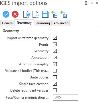
Geometry options (see dialog)
|
Geometry |
Define the wireframe geometry to be imported by activating the related options:
Attempt to simply: As many analytic bodies are represented in IGES files as B surfaces, by selecting this option, the system tries to simplify all imported faces to analytic (planes, cylinders, cones etc.). Validate all bodies (This may be very slow): Activate this option to check the topological and geometric integrity of all bodies. Invalid bodies are deleted. Unite bodies: IGES can represent complex bodies as a series of independent faces or as series of connected faces. This option refers to the former situation where there is no known relationship between the faces. If this option is activated, Designer considers all bodies and attempts to unite them. Single face creation: Many imported bodies have multiple faces. This is usually because the surface representation is Bezier or as a parametric spline surface. Generally, these faces should be tangent but, as the precision is less than that required by Parasolid, the tangency is not recognised. This option moves the surface vertices to attempt to enforce Parasolid tangency and, therefore, reduce the number of faces. Delete redundant vertices and Face/Corner minimisation tolerance: Many IGES B-spline curves are over-defined (too many vertices), and all piecewise surfaces are generally not smooth when converted to a surface. This tolerance is used to:
This is significant internal tolerance. Users should not change it without good reason. |
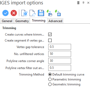
Trimming options (see dialog)
|
Trimming |
Some IGES files represent trimming curves as polylines. A polyline is attached to the surface to be trimmed as a series of B-splines of degree 1. If possible, you should ask your IGES provider for files with trimming curves as curves of a higher degree. If the trimming curves are represented as polylines, the import of files is much more difficult because:
Create curves where trimming fails: The trim loops on a face are sometimes incomplete or ambiguous. As a result, it is not possible to trim the face. Activate this option to create all the trim curves as wireframe geometry so that you can manually trim the faces. Create segment if vertex gap greater than tolerance: If a trim loop is open then a face cannot be trimmed. Activate this option to create as many segments as required to close the loop and specify the Vertex gap Tolerance value. No. unfiltered vertices: Enter the number of vertices which must be present before filtration starts. When the number of vertices is less than this value, the polyline is used without modification. Polyline vertex corner angle: It is important to preserve the 'sharp' corners on the polyline. If the angle between any two segments is greater than this value, the common vertex is preserved and marked as the start/end of a sub-curve within the polyline. The default value is 30 degrees. Polyline vertex filter out angle: Enables redundant vertices to be filtered out. If the angle between any two segments is less than this value, the common vertex is deleted. The default value is 0.5 degrees. If the value is set to 0 degrees, no vertices are filtered.
When the curve has been assessed, by clearing redundant vertices and marking corners, the degree of each sub-curve is raised. This operation is not performed in a mathematically correct manner as it would consume too much memory. The result, however, is that the trimming curve is smooth between corners and the memory requirements are significantly reduced. Trimming Method: As IGES files specify trim curves both parametrically and geometrically, this option allows you to choose the trimming method to apply. |
Advanced options (see dialog)
|
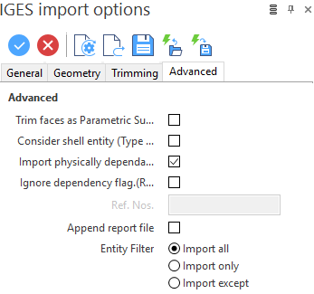
Advanced |
Trim faces as Parametric Surfaces (Type 144): Trimmed faces have a number of representations within IGES. Consider shell entity (Type 514) face direction: Manifold B-rep solids specify a direction on each face that points to the outside of the solid. Activate this option to consider the direction.
Some systems also, incorrectly, use this to define the underlying surface direction. Import physically dependant group entities: Activate this option to Import both logically and physically dependant group entities. Ignore dependency flag. (Results may be incomplete): The records of an IGES file include a status flag which indicates whether the record is a parent or child. When the file is imported, only the parent records are processed because the parents, in turn, refer to their children. Some files are incorrectly formatted and only contain child records and, as a result, nothing will be imported. During the initial stage of import, the file is validated to ensure that there is at least one parent record. If there are no parents, a warning message is displayed. Activate this option to attempt to import such files.
Ref. Nos.: This field allows you to specify the entities to import or not import as function of the Entity Filter options selected.
Append report file: This option allows you to append the report file to the existing file rather than overwrite it when multiple IGES files are imported in sequence. Entity Filter: These options enable you to import (or not import) specific entities. The Ref. Nos field is activated to specify the required entities when Import only or Import except is selected. |
 Hint:
Hint:Further information on Import