Import Interfaces - DWG/DXF - Options
This function imports data from DWG/DXF files by representing the original AutoCAD format as closely as possible.
Import options Dialog Box for DWG/DXF
The import procedure allows you to modify the format and content of the imported file using the configuration options available on the General tab (![]() see dialog) and Linestyles tab (
see dialog) and Linestyles tab (![]() see dialog) of the Import Options dialog.
see dialog) of the Import Options dialog.
- Common icons.
- General options.
- Linestyles options.
Common toolbar
Top Toolbar
![]()
![]()
![]()
These two icons at the top of the dialog box allow you to Apply the current values or to Cancel the current function.
|
Restore system defaults
|
Clicking this icon restores the system default settings. Any other settings are lost. |
|
Restore defaults
|
Clicking this icon allows you to restore the user default settings previously saved by using the Save defaults icon. |
|
Save defaults
|
Clicking this icon allows you to save the current settings as user default settings. |
|
Load parameters from file
|
Clicking this icon allows you to load the required settings from a *.snp file previously saved by using the Save parameters to file icon. |
|
Save parameters to file
|
Clicking this icon allows you to save the current settings into a *.snp file. This option is very useful when you need to define multiple settings for regular use according to your needs. |
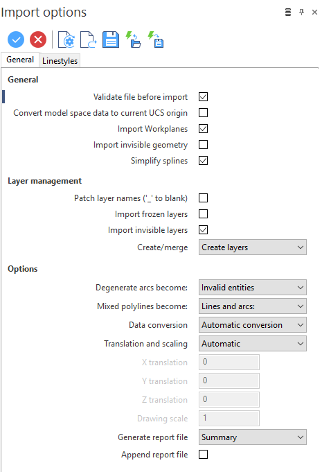
Import options Dialog Box for DWG/DXF: General tab
|
General |
Below you can find the General options to import models coming from DWG/DXF. You can define how Designer manages the different entities. Validate file before import: Activate this option to validate the files to be imported. Any error is sent to the Report file. See the Generate report file option.
As many DWG and DXF files have inconsistent data, the validation finds and corrects them. This manipulation can affect the representation of data which can be slightly different between those files that are validated, and those that are not. Convert model space data to current UCS origin: AutoCAD supports the concept of a User Coordinate System (UCS) that is similar to a Designer workplane. However, it does not differentiate between those coordinates in model or those in paper space. As a result, the AutoCAD UCSs are imported into Designer model space. A UCS is not imported if it is coincident with an existing workplane. The configuration of these options allow you to manage the current UCS:
Import Workplanes: Activate this option to import the Workplanes from the native file. Import invisible geometry: Activate this option to also import the geometry defined as invisible in the native file. Simplify splines: Activate this option to convert, where possible, the splines to points, segments or arcs. |
||
|
Layer management |
Patch layer names ('_' blank): In some versions of AutoCAD, the blank characters of the layer names are replaced by an underscore. This option reverses this status. Import frozen layers: Activate this option to also import the frozen layers from the native file. Import invisible layers: Activate this option to also import the invisible layers from the native file. Create/merge: Select the required option to Create layers or Merge onto active layer. |
||
|
Options |
Degenerate arcs become: An arc is defined as degenerate when the start and end points are coincident. Therefore, it may be both an arc whose internal arc is almost 0 or a circle (360 degrees). AutoCAD draws these as points at the extremes of the arc or as a circle. This option allows you to define how these points have to be represented in Designer:
Mixed polylines become: Select whether the mixed polylines are to be imported as Line and arcs or Profiles. Data conversion: This option allows you to manage the data conversion:
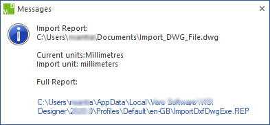
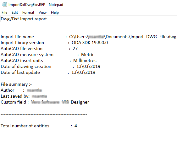
Generate report file: If you need to generate a report, select a Summary or a Standard report; otherwise, choose the No report option. The report file provides information and a warning, if necessary, about the results of the import process. The warning displays when issues arise on data conversion and/or on data translation. If you select the Validate file option, then the validated report is only included in the Standard level report which also includes details of each DWG entity that has caused issues. Note that many of these may be benign (e.g. text with no content). When importing a DWG/DXF with an associated report, a dialog displays ( By clicking on the displayed link, the report automatically opens ( Append report file: Where multiple DWG/DXF files are imported in sequence, this option allows you to append the report file to the existing rather than overwrite it. |
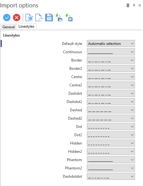
Import options Dialog Box for DWG/DXF: Linestyles tab
AutoCAD has extensive support for different line styles not available in Designer. This tab allows you to define how AutoCAD styles are mapped in Designer. Any style not in the table is assigned the Default Style.
|
Default Style |
This option allows you to define how Designer has to proceed when an unmapped AutoCAD style is found:
|
|
Continuous Border Border2 Centre Centre2 ... ... Dashdotdot |
These parameters display the default mapping between AutoCAD styles and Designer styles. It is possible to modify these settings by choosing the required mapping from the drop down menu associated with each parameter. |
Notes on dimensions
As the two systems have different ways of interpreting the same data, and both have many parameters that do not exist in the other system, it is not possible to create Designer dimensions that are precisely the same as those in AutoCAD.
Designer imports all the standard AutoCAD dimension types (except ordinate) as a dimension and assigns tolerances, dual units, additional text and other parameters as far as is possible.
When you first examine an imported dimension, it will look exactly the same as it does in AutoCAD but when a dimension is edited, Designer rebuilds it and the graphic representation changes. There should not be a significant difference.
![]() Note:
Note:
Also, if most of the current AutoCAD files define the tolerances as a value that can be transferred in Designer without ambiguity, some files include dimensions with text that can both be or not be a tolerance.
In these situations Designer identifies these text values as post dimension text and, when the dimensions are edited and their representation changes, it is necessary to manually edit their parameters.
Further information on Import