Symbols in tolerance annotations
A symbol collection is available in the lower part of the dialog boxes for Geometrical tolerances and Surface finish tolerances.
- You may fill a field with one or more symbols. To do so, select the field and then click on the required symbol(s). A code, for example [s3], will be displayed in the dialog box.
- Alternatively, you may also type the corresponding code (see table below).
- Holding the mouse cursor over a symbol displays an information box about the symbol.
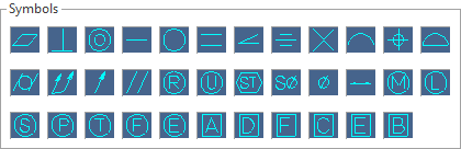
The following symbols are available:
| Symbol | Code | Description |
|---|---|---|
|
|
[s1] | Flatness |
|
|
[s2] | Perpendicularity |
|
|
[s3] | Concentricity |
|
|
[s4] | Straightness |
|
|
[s5] | Circularity |
|
|
[s6] |
Profile diversion in longitudinal section |
|
|
[s7] | Angularity |
|
|
[s8] | Symmetry |
|
|
[s9] | Axis intersection |
|
|
[s10] | Profile of a line |
|
|
[s11] | Position |
|
|
[s12] | Profile of a surface |
|
|
[s13] | Cylindricity |
|
|
[s14] | Total run-out |
|
|
[s15] | Run-out |
|
|
[s16] | Parallelism |
|
|
[s31] | R in circle |
|
|
[s32] | Unilateral |
|
|
[s33] | Statistical |
|
|
[s34] | Spherically |
|
|
[s35] | Diameter |
|
|
[s36] | Double arrow |
|
|
[s23] | Maximum material condition (MMC) |
|
|
[s24] | Least material condition (LMC) |
|
|
[s25] | Regardless of feature size (RFS) |
|
|
[s26] | Projected tolerance zone |
|
|
[s27] | Tangent plane |
|
|
[s28] | Free state |
|
|
[s29] | E in circle |
|
|
[s17] | A in box |
|
|
[s18] | D in box |
|
|
[s19] | F in box |
|
|
[s20] | C in box |
|
|
[s21] | E in box |
|
|
[s22] | B in box |
![]() Notes:
Notes:
- The symbol collection can be extended. The corresponding files, e.g. SYMBOLSET_1_GEOMETRICALTOLERANCE.TXT, are stored in the Designer installation directory in the ...\Library\Common\Cad\Annotations\Symbols sub-folder.
- You may obtain further information about Geometric dimensioning and tolerancing including the use of symbols and their meaning from the corresponding Wikipedia page.