Geometric tolerance
![]()
This function allows you to add geometric tolerance annotations defining the allowable variation for the form and the size of individual features as well as the allowable variation in orientation and location between features.
![]() Note:
Note:
- This function may be used on 3D entities.
Access
- In the Annotations tab, click the
 icon in the Tolerances section of the ribbon.
 - Type geo in the Quick Search field and select Geometric tolerance from the result list.
This opens the Geometric tolerance - Options tab which is displayed along with the ribbon containing the Attributes section. In addition, the Geometrical tolerances dialog box is displayed. ![]() (See dialog box.)
(See dialog box.)
Procedure
- If required, set the annotation layout options in the top section of the dialog box.
- Fill in the Data of the box fields or activate another option under this section.
- Click OK.
- In the graphic area, click on the position point for the annotation.
- Draw the arrow polyline.
- Validate by a Right Mouse click.
The dialog box is temporarily closed and the ribbon containing the Properties icon, Environment, Filters and Attributes sections is displayed.
The dialog box is displayed again allowing you to create another annotation.
![]() Notes:
Notes:
- While positioning the annotation text box, the dialog box can be opened by pressing the [Ctrl] + [Enter] keys of your keyboard. You may also click the
 icon in the ribbon.
 - Pressing the [P] key switches to the Point environment.
- Pressing the [M] key allows you to create multiple arrows.
- When adding an annotation to a 3D entity, you may press the [W] key to swap between the coordinate planes when defining the annotation position.
- Some default values for Geometrical tolerances may be set in the Dimension settings of the application (File > Settings > Dimension).
- You may change some annotation settings for the current project in the Local dimension parameters.
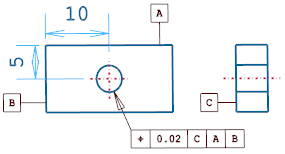
The following example shows geometric tolerance annotations on wireframe entities:
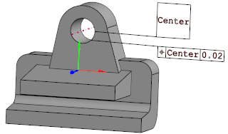
In the following example, geometric tolerance annotations were added to a 3D entity:
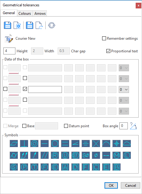
Geometrical Tolerances Dialog Box Options
The following options are available in the General tab of the Geometrical tolerances dialog box:
Top section
The following icons and options are available in the top section of the dialog box:
|
|
Clicking this icon stores the current Data of the box as default. This will be used for the next geometric tolerance annotation. |
|
|
Clicking this icon restores the Data of the box previously saved as default. |
|
|
Clicking this icon allows you to save the current Data of the box as a template document (*.gtt file). |
|
|
Clicking this icon allows you to load a previously saved template file. |
|
|
Clicking this icon allows you to reset the Data of the box. |
 |
Clicking this icon displays the Font dialog box allowing you to select the annotation font. |
|
Remember settings |
Activate this option if you want the application to remember your current layout settings. |
|
Height |
Allows you to define the character height. |
|
Width |
Allows you to define the character width. |
|
Char gap |
Allows you to define the distance between each character. |
|
Proportional text |
Activating this option allows you to apply proportional text. This type of text manages the width of the characters as a ratio parameter related to the height of it according to Windows rules. In this case, the Width and Char gap definition fields are greyed out. |
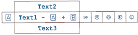
Data of the Box
This section allows you to define the geometrical tolerance data to be displayed in the annotation.
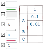
- 1 to 35 fields are available which are displayed in a table that may contain 5 rows and 7 columns:
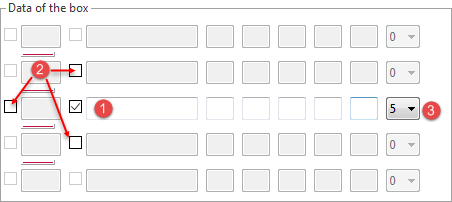
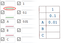
- Initially, only the second field in the third row (1 in the image above) is active.
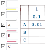
- To activate the first field and/or the rows above or below, check the corresponding check boxes (2 in the image above).
- The other rows become available as you activate the rows above or below the currently active row(s).
- To activate up to 5 other fields on an active row, use the drop-down list at the end of the row (3 in the image above).
- Each field can be filled with strings and/or symbols.
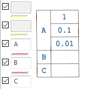
If all the check boxes pointed by the arrows in the above image are active and 5 additional fields are selected in the drop-down list, the annotation table is displayed as follows:
Other options
|
Merge |
If two or more fields are enabled in the first column of the Data of the box table, activating this option allows you to merge the annotation entered in the first column into a single field.
|
|
Base |
Activating this option disables all the fields and data of the Data of the box section and activates the corresponding input field allowing you to enter a text. The shape of this annotation box is always a square:
|
|
Datum point |
Activating this option disables all the other fields and data and allows you to position a datum symbol:
|
|
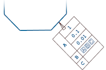
Box angle |
This input field allows you to specify an angle for the placement of the geometrical tolerance text box. |
|
|
Clicking this icon allows you to place the geometrical tolerance text box with the same angle as the selected entity.
You may then proceed to the placement of the annotation box:
|


Symbols
The lower part to the dialog box displays a number of symbols which you can simply add by clicking on a symbol icon.
For further information, refer to the Symbols in tolerance annotations topic.
Editing Geometric Tolerance Annotations
- See Edit dimension.
For further information...