Mirror feature
![]()
The Mirror feature function allows you to move or copy features inside a body by mirror.
![]() Note:
Note:
- The reference area must be substantially equal to the target one from a geometric point of view since the system has to trim the faces in the final area and unite the feature. For analytical faces, the system can extend/shorten them to match the unite conditions between the feature and the body.
Access
- In the Solids tab, click the
 icon in the Pattern section of the ribbon.
 - Type mirror in the Quick Search field and select Mirror feature from the result list.
This opens the Mirror feature - Options tab which is displayed along with the ribbon containing the Options, Filters and Selection sections and displays the Mirror feature dialog box. ![]() See dialog box.
See dialog box.
Procedure
In the following steps, confirmation by Right Mouse click may be required if Multi-select ![]() is active in the Selection options.
is active in the Selection options.
- Using the Face selection filters, select the faces to mirror.
- Using the Point selection filters, define the application point of the mirror.
- Using the Direction options, select the mirror plane direction and validate.
- If required, drag the green sphere to change the Mirror plane point.
- Validate, either by a Right Mouse click or by clicking the
 icon in the dialog box.
A preview is displayed with respect to the selected elements and options.
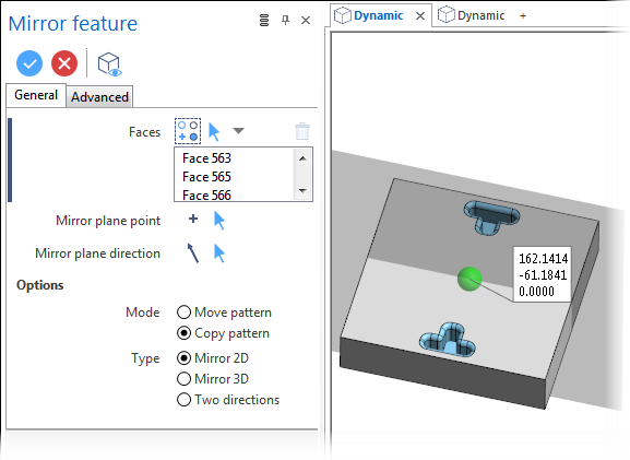
Mirror feature Dialog Box Options
The following options are available in the Mirror feature dialog box:
Top Toolbar
![]()
![]()
![]()
These two icons at the top of the dialog box allow you to Apply the current values or to Cancel the current function.
Preview generation is Automatic if this option is active in the dialog box menu accessed by clicking on the  icon. If this option is not active, click on the
 ![]() icon. If preview generation is not possible, the icon is greyed out.
icon. If preview generation is not possible, the icon is greyed out.
Faces
The Faces field lists the identifiers of the selected faces.
Clicking on the ![]()
![]() icon switches back into the selection mode allowing you to modify your selection by selecting/unselecting elements in the graphic area. You may click the
icon switches back into the selection mode allowing you to modify your selection by selecting/unselecting elements in the graphic area. You may click the ![]() icon and then click Reset selection to reset your whole selection. If you want to delete elements within your selection, select the required elements and then click the
icon and then click Reset selection to reset your whole selection. If you want to delete elements within your selection, select the required elements and then click the ![]() icon above the list field. You may use the [Ctrl] + [A] shortcut to select all of the elements. Use the
icon above the list field. You may use the [Ctrl] + [A] shortcut to select all of the elements. Use the ![]() icon (or Right Mouse click) to Validate your selection. The
icon (or Right Mouse click) to Validate your selection. The ![]() icon (or [Esc]) cancels the selection mode.
icon (or [Esc]) cancels the selection mode.
Mirror plane point
Allows you to define the reference point for the mirror plane. This point is then represented by a green sphere that you can drag in the graphic area to change the point position. Clicking on the ![]()
![]()
Mirror plane direction
Allows you to define the direction of the mirror plane. In the graphic area, a transparent plane representation is displayed. Clicking on the ![]()
![]()
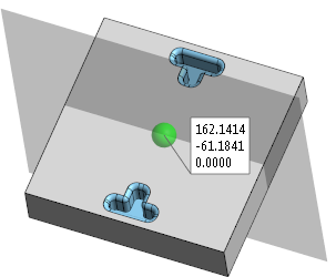
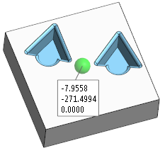
The following example shows a mirror plane point and plane representation:
Options
|
Mode: |
|
|
Move pattern |
Activate this option if you want to apply a translation to the selected elements. |
|
Copy pattern |
Activate this option if you want to make a single copy leaving the initially selected elements in place. |
|
Type: |
|
|
Mirror 2D |
Select this option to apply a mirror with respect to a selected or user defined axis. |
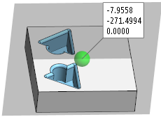
In the following examples, a 2D mirror has been applied to the blue faces with respect to the application point in the centre of the top face of the cuboid. The mirror plane was then defined respectively in the X-axis, in the Y-axis and in view direction. Note that there is no plane representation with this option:
|
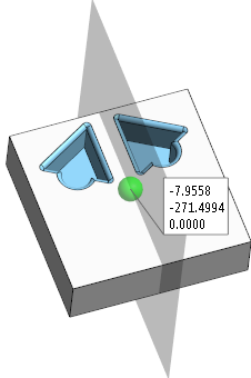
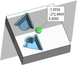
Mirror 3D |
Select this option to apply a mirror in space. In this case, the mirror is made on a plane in the direction of the selected axis. |
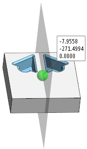
In the following examples, a 3D mirror has been applied to the blue faces with respect to the application point in the centre of the top face of the cuboid. It was then applied in the X-axis and the Y-axis. The application point was changed and the mirror applied in the Z-axis:

|
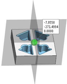
Two directions |
Activate this option to apply the mirror in a single step in two directions as shown in the following illustration: |
Information Field
The field at the bottom of the dialog box displays information about missing data, errors or actions.
Advanced Tab
Refer to the Feature Transformation - Advanced Options topic for further information about the options to be found on this tab.