Involute Curves
![]()
This function allows you to create involute curves based on a reference circle.
Mechanical curves are often used in CAM generation and where mechanical movements are guided by rotating machinery.
An involute is the locus of a point on a circle as it is unwrapped from the circle maintaining a taut and, therefore, tangential line.
Access
- In the Wireframe tab, select
 Involute from the drop-down list under the
  Hyperbola entry in the Curves section of the ribbon.
 - Type invol in the Quick Search field and select Involute from the result list.
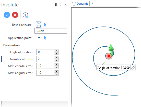
This opens the Involute - Options tab which is displayed along with the ribbon containing the Filters section. In addition, the Involute dialog box is displayed. ![]() See dialog box.
See dialog box.
Procedure
- Select the base circle or arc.
- Select the Application point.
- Using the slider in the graphic area and the input fields in the dialog box, define the curve shape.
-
Validate, either by a Right Mouse click or by clicking the
 icon in the dialog box.
![]() Notes:
Notes:
-
Clicking on the Measurement
 icon on the slider label or alongside the active value input field in the dialog box displays the Measurement Menu which helps you to define specific points.
 -
You can use simple JavaScript expressions and mathematical formulas to define the required values.
Dialog Box Options
The following options are available in the Involute dialog box:
Top Toolbar
![]()
![]()
![]()
These two icons at the top of the dialog box allow you to Apply the current values or to Cancel the current function.
Preview generation is Automatic if this option is active in the dialog box menu accessed by clicking on the  icon. If this option is not active, click on the
 ![]() icon. If preview generation is not possible, the icon is greyed out.
icon. If preview generation is not possible, the icon is greyed out.
Base circle/arc
This field displays the type of the selected reference element (circle or arc).
Clicking on the ![]()
![]()
![]() icon (or Right Mouse click) to Validate your selection. The
icon (or Right Mouse click) to Validate your selection. The ![]() icon (or [Esc]) cancels the selection mode.
icon (or [Esc]) cancels the selection mode.
Application point
Defines the application point of the involute curve.
Clicking on the ![]()
![]()
![]() icon (or Right Mouse click) to Validate your selection. The
icon (or Right Mouse click) to Validate your selection. The ![]() icon (or [Esc]) cancels the selection mode.
icon (or [Esc]) cancels the selection mode.
Parameters
The following parameters allow you to define the involute curve:
|
Angle of rotation |
This is the angle at which the cycloid is drawn with respect to the horizontal passing through the application point. |
|
Number of turns |
Enter the number of turns to be created. |
|
Max. chordal error / Max. angular error |
These parameters define the graphic representation of circles. The Max. chordal error is the maximum allowed distance between a chord and the circumference of the arc or circle. The Max. angular error is the maximum allowed sum of the angles between the chord and the circumference. |
Information Field
The field at the bottom of the dialog box displays information about missing data, errors or actions.