Export Interfaces - 3DPDF, ACIS, STEP and VDA - Options
These options allow you to export files from Designer to the following formats:
- 3DPDF files in *.pdf format which print a 3D Model as a PDF.
- ACIS and ACIS Binary files in *. sat, *.asat, *.sab and *.asab formats.
- STEP files in *.stp format.
- VDA files in *.vda format.
ACIS is Spatial's 3D modelling component used in various CAD/CAM applications.
STEP is the informal name of an ISO standard for the computer-interpretable representation and exchange of product manufacturing information. Designer exports to STEP models and, optionally, wireframe elements with their associated attributes. It does not export annotations.
VDA does not support layers or colour attributes. In order to provide a partial potential support for layers, Designer exports all entities belonging to the same layer in a VDA SET. The VDA SET can have a name of up to 8 characters and, therefore, Designer creates a SET name consisting of the first 5 characters of the layer name and the 3 characters that represent the layer index.
VDA files can selectively export geometry and solids. All wireframe geometric entities are exported as splines. VDA files cannot include annotation or entity attributes (colour, linestyle etc).
Export options Dialog Box for 3DPDF, ACIS, STEP and VDA
Designer allows you to manage the content of the exported files using the configuration options available in the Export options dialog: ![]() 3DPDF,
3DPDF, ![]() ACIS,
ACIS, ![]() STEP or
STEP or ![]() VDA.
VDA.
The dialog consists of:
Common toolbar
Top Toolbar
![]()
![]()
![]()
These two icons at the top of the dialog box allow you to Apply the current values or to Cancel the current function.
|
Restore system defaults
|
Clicking this icon restores the system default settings. Any other settings are lost. |
|
Restore defaults
|
Clicking this icon allows you to restore the user default settings previously saved by using the Save defaults icon. |
|
Save defaults
|
Clicking this icon allows you to save the current settings as user default settings. |
|
Load parameters from file
|
Clicking this icon allows you to load the required settings from a *.snp file previously saved by using the Save parameters to file icon. |
|
Save parameters to file
|
Clicking this icon allows you to save the current settings into a *.snp file. This option is very useful when you need to define multiple settings for regular use according to your needs. |
Common parameters
|
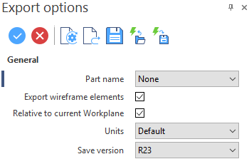
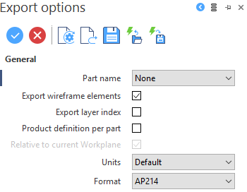
Part name: You can choose between the following options relating to name of the part being exported :
|
|
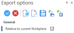
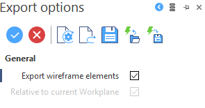
Export wireframe elements: Select this option to export the wireframe elements in the receiver format. |
|
Relative to current Workplane: The models are usually exported relatively to the World Absolute co-ordinate System (View ABS). This option is available only if the current workplane is not the absolute one, and its activation allows you to export the model relatively to the co-ordinate system (View REL) of the current workplane.
For more details about:
|
Proprietary parameters
|
ACIS |
Units: Select the required units from the drop-down menu:
Save Version: Choose the ACIS version to which you need to export the Designer file. |
|
STEP |
Export layer index: Many CAD systems primarily identify their layers by index; the layer name is an optional second identifier and the description is an optional third identifier. In fact, when a body is assigned to a layer or a layer is added to a filter, this is done with an integer index. Unfortunately, the STEP definition provides only two textual fields (name and description) but no storage for the index. Check this option to preserve the layer index as the primary identifier by writing it in the name field of the STEP data. The source name, if available, is then written to the description field of the STEP data. Product definition per part: Activate this option to write the file with a single Product Definition node for all the bodies in the Part document. If not activated, by default, each body in the Part document will have its own Product Definition node. Format: Select the STEP format to which you need to export the Designer file from the drop-down menu:
|
Further information on Export