Cuboid
![]()
The Cuboid function is used to create a solid body by defining a rectangular base and a height.
Access
- In the Designer tab, click the
 icon in the Solids section of the ribbon.
 - In the Solids tab, click the icon in the Forms section of the ribbon.
- Type cube in the Quick Search field and select Cuboid from the result list.
- You may also use the Ctrl + B shortcut key. This key is defined by default but another key combination may have been selected. Refer to Shortcut keys for further information.
In all cases, this opens the Cuboid - Options tab which is displayed along with the ribbon containing the Filters and Attributes sections. The Cuboid dialog is also displayed. ![]() See dialog box.
See dialog box.
Procedure
- Select the Creation method. When you start the function for the first time, the Select three points creation method is active.
- Select the Application Point for the solid block to be created and, if required, the Boolean Operation.
Note that activation of the Pocket/Boss creation mode in the Advanced tab is only possible if Select position is active.
Select Three Points option active
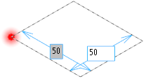
- In the graphic area, click three points:
- The first point is the application point.
- The second point defines the size of the base rectangle.
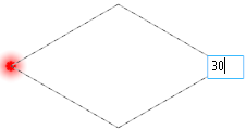
- The third point defines the height of the block.
The dimensions are displayed as you move the mouse.
Validation is automatic when you click the third point.
![]() Notes:
Notes:
- Alternatively, you may also use the distance labels to enter the required dimensions. Press [Enter] after having entered a value to switch to the next value input field or to validate the cuboid.
-
When the Creation method is by point selection, the [Esc] key works as follows:
- Pressing the [Esc] key before selecting the first point closes the command.
- Pressing the [Esc] key after having selected the first or second point resets the point selection. The user must select the first point again.
-
When the Select point method is active, pressing the [Pg Up] key on your keyboard allows you to successively undo your point selection.
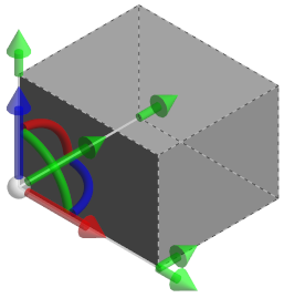
Select Position option active
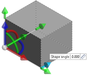
- In the graphic area, click on the application point of the cuboid to display the sliders along with a preview of the cuboid to be created based on the most recently used parameters.
Using the sliders in the graphic area:
- Click and hold down the Left Mouse button on the Length slider and drag it to the required length. Click to set the length.
- If required, use the perpendicular second arrow displayed with the length slider to define a Shape angle.
- Using the same method, define the Width and the Height of the cuboid.
-
Validate, either by a Right Mouse click or by clicking the
 icon in the dialog box.
 - You may click the active slider arrow to adjust the value of the corresponding dimension in the value input box of the slider label.
-
Refer to the Slider Positioning and Movement section for further information about slider usage.
-
The label of the corresponding Slider element is displayed when holding the mouse cursor over it or if you click it.
-
You can use simple JavaScript expressions and mathematical formulas to define the required values.
- Clicking on the Measurement
 icon on the slider label or alongside the active value input field in the dialog box displays the Measurement Menu which helps you to define specific points.
 - Pressing the [W] key of your keyboard allows you to toggle between wireframe and shaded preview display of the entity being created or moved.
-
If mandatory values are missing or if erroneous values are entered, an exclamation mark
 is displayed in the relevant slider value input box and the background of the corresponding parameter input box in the dialog box is displayed in red.
 - You can lock the dimension labels.
![]() Notes:
Notes:
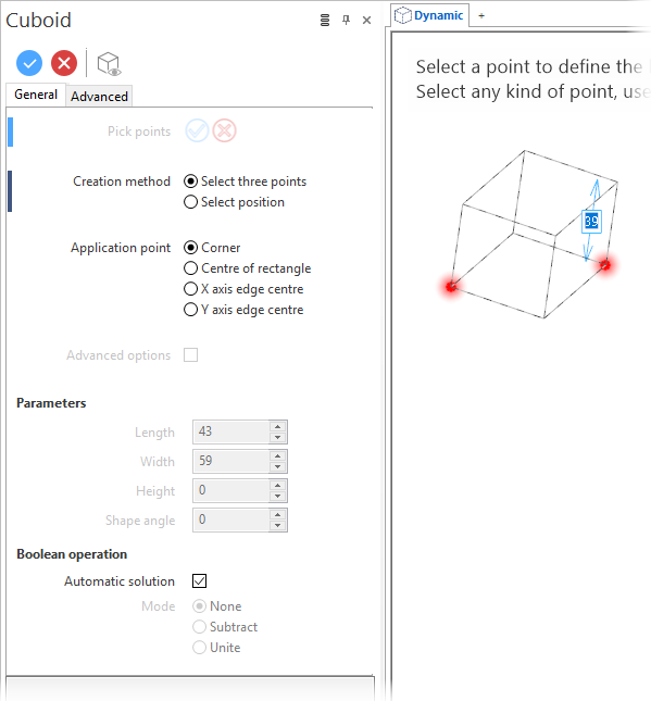
Cuboid Options - General Tab
The General tab of the Cuboid dialog box contains the following options:
Top Toolbar
![]()
![]()
![]()
These two icons at the top of the dialog box allow you to Apply the current values or to Cancel the current function.
Preview generation is Automatic if this option is active in the dialog box menu accessed by clicking on the  icon. If this option is not active, click on the
 ![]() icon. If preview generation is not possible, the icon is greyed out.
icon. If preview generation is not possible, the icon is greyed out.
Method
|
Pick points |
Clicking the |
|
Creation method: |
|
|
Select three points |
Allows you to define a cuboid by point selection: two points to define the base rectangle and a third one to define the height. |
|
Select position |
Activate this option to start the cuboid creation by clicking on a position point:
|
|
Select either Corner, Centre of rectangle, X axis edge centre or Y axis edge centre.
|
|
|
Advanced options |
This option become available if Select position is the creation method. Checking this box activates the Pocket/Boss creation mode in the Advanced tab. |
Parameters
The values in this section are automatically updated as you move the sliders in the graphic area. You may also manually enter or adjust the corresponding values.
|
Length |
Allows you to define the length of the cuboid. |
|
Width |
Allows you to define the width of the cuboid. |
|
Height |
Allows you to define the height of the cuboid. |
|
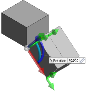
Shape angle |
Allows you to define an angle with respect to the application point: |
In addition to the dimension arrows, using slider positioning if required, you may define the position and the inclination of the solid being created.
Boolean Operation
This section allows you to select a Boolean operation to apply during solid creation. Select either None, Subtract or Unite.
In addition, an Automatic solution option is available. Activating this option automatically applies a Boolean operation according to the following rules:
- If there is no contact or intersection, the Boolean mode is None.
- If there is only contact, the Boolean mode is Unite.
- If there is intersection, the Boolean mode is Subtract.
Information Field
The field at the bottom of the dialog box displays information about missing data, errors or actions.
Colour Management
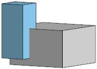
You may use the Attributes toolbox to modify the colour of the entities created. With respect to the active Boolean operation, the colours are managed as follows:
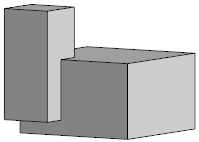
- If None is the Boolean mode, both entities keep their own colour:
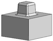
- If Unite is the Boolean mode, the added entity inherits the colour from the initial one. This also applies to any connection shapes added when the Advanced mode is active.
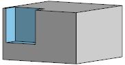
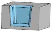
- If Subtract is the Boolean mode, the created faces inherit the colour from the subtracted entity. This also applies to any connection shapes added when the Advanced mode is active.
For further information...