Text leader
![]()
This function allows you to display text information that points to a specific area of the drawing.
Access
- In the Annotations tab, click the
 icon in the Leaders section of the ribbon.
 - Type text in the Quick Search field and select Text leader from the result list.
This opens the Text leader - Options tab which is displayed along with the ribbon containing the General, Environments, Filters and Attributes sections.
Procedure
- Activate the appropriate Environment and Filters options.
- Click on the reference element to position the arrow of the text leader.
- Click on a point to draw the leader.
- If necessary, click on other points to draw the leader with multiple segments.
- Press the [T] key or click the Properties
 icon. This allows you to enter and configure text after validation.
 - The Text data Input/Modification dialog box is displayed.
- Enter your text and define parameters (See Text Data Input/Modification).
- Click OK to validate and close the dialog box.
- Right click to validate.
Text Data Input/Modification
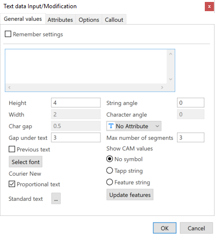
General Values Tab
|
Remember settings |
Activate this option to save your current settings. |
|
Text field |
Enter/Modify the text in this field. You can use keyboard shortcuts to add special characters:
|
|
Height |
Enter the height of characters in this field. |
|
Width |
Enter the width of characters in this field (only for static texts). It is disabled if the Static proportional text option is activated. |
|
Char gap |
Enter the distance between each character in this field. It is disabled if the Static proportional text option is activated. |
|
Gap under text |
Enter the distance between the text and the leader in this field. |
|
Previous text |
Activate this option if you to want to reuse text from the previous text leader. |
|
Select font |
Click this button to define the font parameters. |
|
Static proportional text |
When this option is activated, proportional text is applied; the width of characters is calculated as a ratio relative to the height of characters. |
|
Standard text |
This option allows you to select predefined text in the application:
|
|
String angle |
Enter the angle for the entire string of characters in this field. |
|
Character angle |
Enter the angle of characters in this field (only for static texts). It is disabled if the Proportional text option is activated. |
|
Text attribute |
Select the text attribute in this drop-down list: Underline, Overline, etc. |
|
Max number of segments |
Enter the maximum number of segments, between 1 and 3, for the leader in this field. |
|
Show CAM values |
When you select entities with CAM attributes, you can generate a leader dimension with the CAM values (e.g. Diam. 8 Rough Boring or M12) by activating one of the following options:
|
|
Update features |
Click this button to apply description strings from the Feature Manager. |
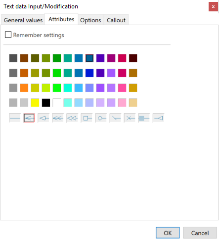
Attributes Tab
|
Remember settings |
Activate this option to save your current settings. |
|
Colours |
Select the text colour. |
|
Arrow style |
Select the arrow style for the leader. |
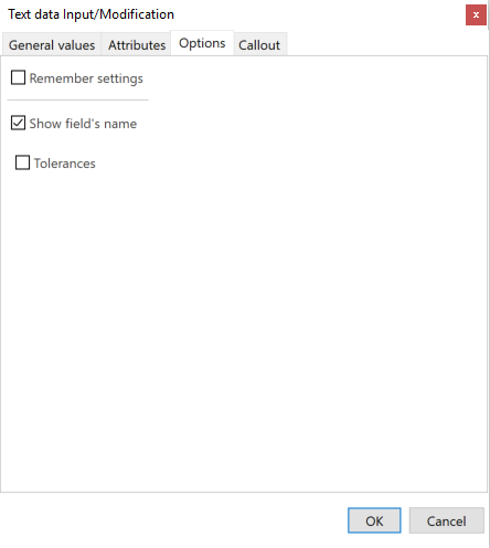
Options Tab
|
Remember settings |
Activate this option to save your current settings. |
|
Show field's name |
Activate/Deactivate this option to show/hide the name of the field. |
|
Tolerances |
This option is available when you have selected a circle or circular edge. Activate/Deactivate it to show/hide the tolerances defined in the Feature Manager. |
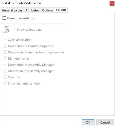
Callout Tab
This tab allows you to show information defined in the Feature Manager. The options in this tab are available when selecting the edge of a hole.
|
Remember settings |
Activate this option to save your current settings. |
|
Show callout data |
Activate this option to show/hide all the options of the Callout tab. |
|
Cycle association |
Activate/Deactivate this option to show/hide the drilling cycle associated with the feature. |
|
Description in Feature properties |
Activate/Deactivate this option to show/hide the description defined in the Feature configuration file. |
|
Dimension defined in Feature properties |
Activate/Deactivate this option to show/hide the dimension defined in the Feature configuration file. |
|
Diameter value |
Activate/Deactivate this option to show/hide the diameter value. |
|
Description in Assembly Manager |
Activate/Deactivate this option to show/hide the description of the associated standard element in the Assembly Manager. |
|
Dimension in Assembly Manager |
Activate/Deactivate this option to show/hide the dimension of the associated standard element in the Assembly Manager. |
|
Quantity |
Activate/Deactivate this option to show/hide the quantity of this element in the same plane with the same direction. |
|
Show diameter symbol |
Activate/Deactivate this option to show/hide the diameter symbol. |
Editing Existing Text Leaders
- See Edit dimension.