Scaling
![]()
The Scaling function allows you to apply a scale to the selected entities.
Access
- In the Designer tab, click the
 icon in the Standard section of the ribbon.
 - In the Wireframe tab, click the icon in the Modify section of the ribbon.
- In the Solids tab, click the icon in the Operations section of the ribbon.
- Type scale in the Quick Search field and select Scaling from the result list.
This opens the Scaling - Options tab which is displayed along with the ribbon containing the General, Options, Filters and Selection sections.
Procedure
In the following steps, confirmation by Right Mouse click may be required if Multi-select ![]() is active in the Selection options.
is active in the Selection options.
- Using the Object selection filters, select the entities to scale.
- Using the Point selection filters, define the application point to display the Scaling dialog box.
 See dialog box.
- Select the required options according to the result you want to achieve.
- Click the different Scale slider arrows and drag them to achieve the required scale. Clicking on the Measurement
 icon on the slider label displays the Measurement Menu which helps you to define specific points. You may also enter the scale values in the slider input boxes or in the relevant Scale ... field of the dialog box.
 -
Validate, either by a Right Mouse click or by clicking the
 icon in the dialog box.
![]() Notes:
Notes:
- The application point does not need to be positioned on the entities to be scaled. It only defines the position of the scaled entities after function application and does not affect the geometric result.
-
Pressing the [W] key of your keyboard allows you to toggle between wireframe and shaded preview display of the entity being created.
- If the Move elements option is active, you may use the [H] key on your keyboard to hide/show the dotted outline of the original entities.
Dialog Box Options
The following options are available in the Scaling dialog box:
Top Toolbar
![]()
![]()
![]()
These two icons at the top of the dialog box allow you to Apply the current values or to Cancel the current function.
Preview generation is Automatic if this option is active in the dialog box menu accessed by clicking on the  icon. If this option is not active, click on the
 ![]() icon. If preview generation is not possible, the icon is greyed out.
icon. If preview generation is not possible, the icon is greyed out.
Parameters
|
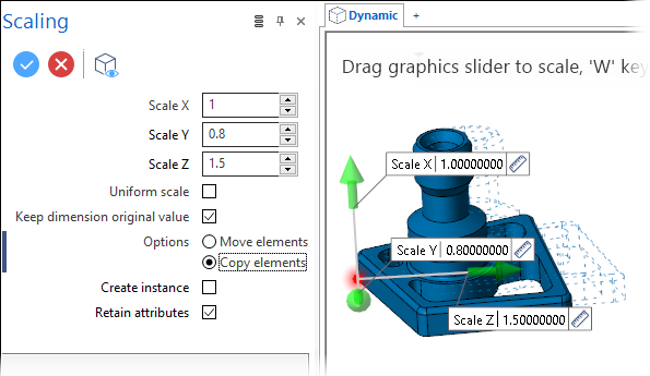
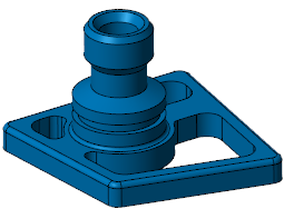
Scale X, Y or Z |
These three input fields allow you to define the scaling factors for the corresponding axis. Values < 1 decrease the size and values > 1 increase the size of the selected entities in the corresponding axis. Alternatively, you may also use the slider arrows in the graphic area or their input boxes. In the following example, the blue solid is selected for scaling. With respect to the red application point and different scaling factors, the second image shows the result:
|
|
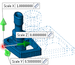
Uniform scale |
This option is active by default. It allows you to apply the same scaling factor to all the axes. In this case, only the Scale X field is available allowing you to define the global scaling factor. In the following example, the same blue body is selected for scaling with respect to the red application point and a uniform scaling factor:
|
|
Keep dimension original value |
Activate this option to leave dimension annotations with their original value. Instead of adapting associative dimension annotations by the scale factor, the real size of the object remains displayed. |
Options
Refer to the Ribbon Options for Entity Translation, Rotation, Mirror and Scaling topic for further information about these entries.
Information Field
The field at the bottom of the dialog box displays information about missing data, errors or actions.