Move Faces
![]()
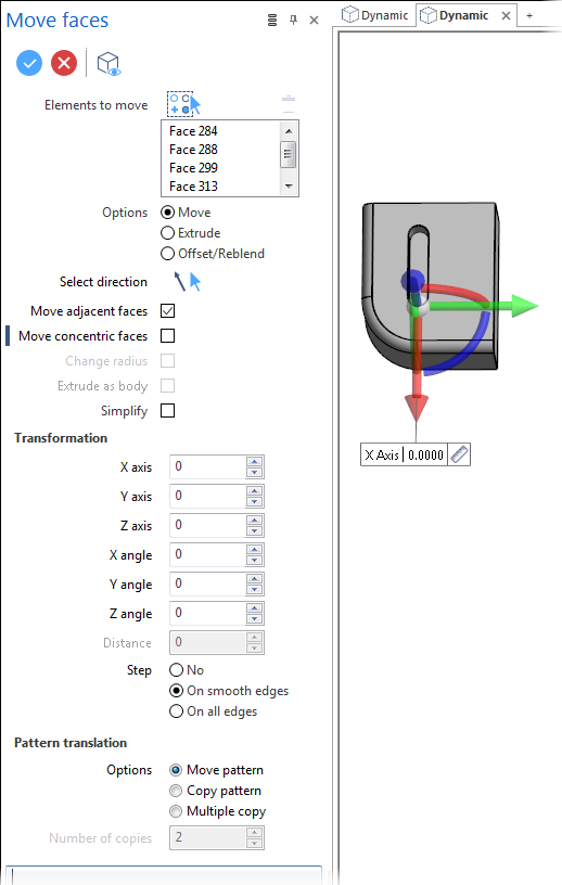
The Move Faces function allows you to move, extrude or offset/reblend selected faces using several methods.
![]() Note: This command may be applied to mesh entities.
Note: This command may be applied to mesh entities.
Access
- Click the
 icon in the Solids section of the Designer tab.
 - Activate the Solids tab and then click the icon in the Operations section of the ribbon.
-
Type Move in the Quick Search field and select Move from the result list.
In all cases, this opens the Move Options tab which is displayed along with the ribbon containing the Options, Filters and Selection sections. In addition, the Move faces dialog box is displayed. ![]() See dialog box.
See dialog box.
Procedure
In the following steps, confirmation by Right Mouse click may be required if Multi-select ![]() is active in the Selection options.
is active in the Selection options.
- Using the Face selection filters, select the face(s) which you want to move.
- Based on the analyses of the selected faces, the system automatically selects the most appropriate option among Move, Extrude or Offset/Reblend. If required, select another option according to the result you want to obtain.
![]() Note: Slider display is different for the three options.
Note: Slider display is different for the three options.
- Set the options defining which faces or edges will be impacted by transformations to apply.
- Either by using the slider widget in the graphic area (change its position as required) or by directly entering the values in the Transformation fields, apply the required transformations:
- Validate, either by a Right Mouse click or by clicking the
 icon in the dialog box.
![]() Notes:
Notes:
-
You can use simple JavaScript expressions and mathematical formulas to define the required values.
- Clicking on the Measurement
 icon on the slider label or alongside the active value input field in the dialog box displays the Measurement Menu which helps you to define specific points.
 - If you change the position of the slider, its new position is retained for further actions.
-
If mandatory values are missing or if erroneous values are entered, an exclamation mark
 is displayed in the relevant slider value input box and the background of the corresponding parameter input box in the dialog box is displayed in red.
Dialog Box Options
The following options are available in the Move faces dialog box:
Top Toolbar
![]()
![]()
![]()
These two icons at the top of the dialog box allow you to Apply the current values or to Cancel the current function.
Preview generation is Automatic if this option is active in the dialog box menu accessed by clicking on the  icon. If this option is not active, click on the
 ![]() icon. If preview generation is not possible, the icon is greyed out.
icon. If preview generation is not possible, the icon is greyed out.
Elements to move
The Elements to move field lists the identifiers of the selected elements.
Clicking on the  icon switches back into the selection mode allowing you to modify your selection by selecting/unselecting elements in the graphic area. Use the
 ![]() icon (or Right Mouse click) to Validate your selection. The
icon (or Right Mouse click) to Validate your selection. The ![]() icon (or [Esc]) cancels the selection mode. If you want to delete elements within your selection, select the required elements and then click the
icon (or [Esc]) cancels the selection mode. If you want to delete elements within your selection, select the required elements and then click the ![]() icon above the list field. You may use the [Ctrl] + [A] shortcut to select all of the elements.
icon above the list field. You may use the [Ctrl] + [A] shortcut to select all of the elements.
Options
|
Move |
Activate this option to move the selected items. |
|
Extrude |
Activate this option to extrude the selected items. |
|
Offset/Reblend |
Activate this option to apply an offset to the selected faces or to change the radius value of concentric faces such as blends or cylinders. |
![]() Note: The Move and Offset/Reblend options interact with the Move adjacent faces and Move concentric faces options (see below).
Note: The Move and Offset/Reblend options interact with the Move adjacent faces and Move concentric faces options (see below).
|
Select direction |
If you do not want to use the default direction, click the
You may also use the Direction definition options that become available on the ribbon at function selection. |
|
Move adjacent faces |
This option is available when either Move or the Offset/Reblend operation is selected. If it is active, it moves all of the adjacent faces along with the selected elements. |
|
Move concentric faces |
This option is available when either Move or the Offset/Reblend operation is selected. When moving circular items with this option active, it simultaneously moves concentric faces. |
|
Change radius |
This option is available if a cylindrical face is selected. It allows you to change the radius by entering a new Distance. |
|
Extrude as body |
This option is available when the Extrude operation is selected. It allows you to extrude the selected items as a body. |
|
Simplify |
Activate this option to remove all of the unnecessary lines created by the applied transformations. |
 icon to select another direction:
 Transformation
This section allows you to enter or adjust the X, Y and Z axis and angle transformation values or to specify a distance if the Offset/Reblend option is active. They are automatically updated according to the slider movements in the graphic area.
The Step section allows you to select an option from No, On smooth edges and On all edges. This section is not available with the Extrude option.
Pattern translation
The options in this section are only available if the Move method has been selected. They allow you to define whether you want to move or copy the selected elements.
|
Options |
Move pattern: Activate this option if you want to apply a translation to the selected elements. Copy pattern: Activate this option if you want to make a single copy leaving the initially selected elements in place. Multiple copy: Activate this option if you want to make several copies of the selected elements. |
|
Number of copies |
This field becomes active if Multiple copy is selected allowing you to enter the number of copies to be made. |
Information Field
The field at the bottom of the dialog box displays information about missing data, errors or actions.
See also...