Convert to mesh
![]()
The Convert to mesh function allows you to convert solid or sheet bodies into a triangle mesh entity.
Access
- Activate the Solids tab and then click the
 icon in the Mesh section of the ribbon.
 -
Type mesh in the Quick Search field and select Convert to mesh from the result list.
This opens the Convert to mesh - Options tab which is displayed along with the ribbon containing the Options, Filters and Selection sections and displays the Solid to mesh dialog box. ![]() See dialog box.
See dialog box.
Procedure
In the following steps, confirmation by Right Mouse click may be required if Multi-select ![]() is active in the Selection options.
is active in the Selection options.
- Select the solids to convert into mesh entities.
- If required, adjust the default options.
- Validate, either by a Right Mouse click or by clicking the
 icon in the dialog box.
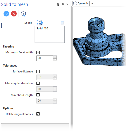
Solid to Mesh Dialog Box Options
The following options are available in the Solid to mesh dialog box:
Top Toolbar
![]()
![]()
![]()
These two icons at the top of the dialog box allow you to Apply the current values or to Cancel the current function.
Preview generation is Automatic if this option is active in the dialog box menu accessed by clicking on the  icon. If this option is not active, click on the
 ![]() icon. If preview generation is not possible, the icon is greyed out.
icon. If preview generation is not possible, the icon is greyed out.
Solids
The Solids field lists the identifiers of the selected solids.
Clicking on the  icon switches back into the selection mode allowing you to modify your selection by selecting/unselecting elements in the graphic area. Use the
 ![]() icon (or Right Mouse click) to Validate your selection. The
icon (or Right Mouse click) to Validate your selection. The ![]() icon (or [Esc]) cancels the selection mode. If you want to delete elements within your selection, select the required elements and then click the
icon (or [Esc]) cancels the selection mode. If you want to delete elements within your selection, select the required elements and then click the ![]() icon above the list field. You may use the [Ctrl] + [A] shortcut to select all of the elements.
icon above the list field. You may use the [Ctrl] + [A] shortcut to select all of the elements.
Faceting
|
Maximum facet width |
Activate this option to define the maximum facet width in the corresponding value input field. |
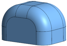
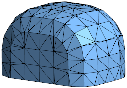
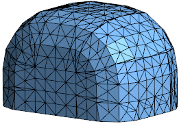
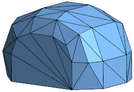
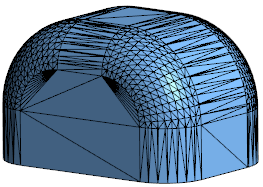
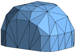
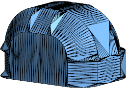
The following example shows the initial solid converted into a mesh entity using the default facet width and a reduced facet width:
Tolerances
|
Surface distance |
Activate this option to adjust the surface distance in the corresponding value input field. |
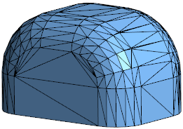
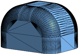
In the following example, the Surface distance value was set to 5 in the first image and to 0.1 in the second one:
|
Max angular deviation |
Activate this option to adjust the maximum angular deviation. |
In the following example, the Max angular deviation value was set to 20 in the first image and to 5 in the second one:
|
Max chord length |
Activate this option to adjust the maximum chord length. |
In the following example, the Max chord length value was set to 20 in the first image and to 2 in the second one:
Options
|
Delete original bodies |
Activate this option if you want to delete the original bodies. |
![]() Note: Clicking on the Measurement
Note: Clicking on the Measurement ![]() icon alongside the active value input box displays the Measurement Menu which helps you to define specific points.
icon alongside the active value input box displays the Measurement Menu which helps you to define specific points.
Information Field
The field at the bottom of the dialog box displays information about missing data, errors or actions.