Extract mesh edges
![]()
The Extract mesh edges function allows you to identify "sharp" edges according to a given tolerance. The aim is to extract them as elements and to imprint them on the mesh in order to separate those faces from the rest of the mesh.
![]() Note:
Note:
- Once the faces identified, you may use the Mesh to surface command to convert them into surfaces.
Access
- Activate the Solids tab and then click the
 icon in the Mesh section of the ribbon.
 -
Type mesh or extract in the Quick Search field and select Extract mesh edges from the result list.
This opens the Extract mesh edges - Options tab which is displayed along with the ribbon containing the Environments, Options, Filters, Selection and Attributes sections and displays the Extract mesh edges dialog box. ![]() See dialog box.
See dialog box.
Procedure
In the following steps, confirmation by Right Mouse click may be required if Multi-select ![]() is active in the Selection options.
is active in the Selection options.
- Select the mesh elements for edge extraction.
- If required, adjust the tolerances and activate the required options.
- Validate, either by a Right Mouse click or by clicking the
 icon in the dialog box.
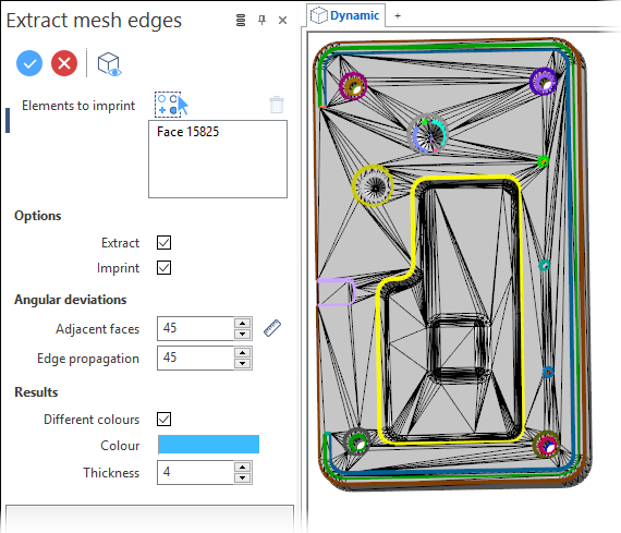
Extract Mesh Edges Dialog Box Options
The following options are available in the Extract mesh edges dialog box:
Top Toolbar
![]()
![]()
![]()
These two icons at the top of the dialog box allow you to Apply the current values or to Cancel the current function.
Preview generation is Automatic if this option is active in the dialog box menu accessed by clicking on the  icon. If this option is not active, click on the
 ![]() icon. If preview generation is not possible, the icon is greyed out.
icon. If preview generation is not possible, the icon is greyed out.
Elements to imprint
This field lists the identifiers of the selected elements.
Clicking on the  icon switches back into the selection mode allowing you to modify your selection by selecting/unselecting elements in the graphic area. Use the
 ![]() icon (or Right Mouse click) to Validate your selection. The
icon (or Right Mouse click) to Validate your selection. The ![]() icon (or [Esc]) cancels the selection mode. If you want to delete elements within your selection, select the required elements and then click the
icon (or [Esc]) cancels the selection mode. If you want to delete elements within your selection, select the required elements and then click the ![]() icon above the list field. You may use the [Ctrl] + [A] shortcut to select all of the elements.
icon above the list field. You may use the [Ctrl] + [A] shortcut to select all of the elements.
Options
|
Extract |
Activate this option to extract the mesh edges as polylines and, if enabled, create regions which can then be extruded. The initially selected mesh body remains unchanged. |
|
Imprint |
Activate this option to imprint the mesh edges in order to delimit the extracted areas as individual mesh entities. These mesh faces may then be converted to surfaces. |
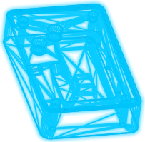
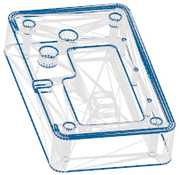
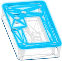
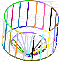
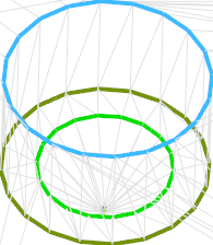
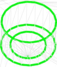
In the following example, the first image shows the selected mesh element. The result after edge extraction is shown in the second image.
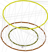
In the third image, only Extract option was active. It shows the created polylines/region:
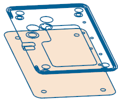
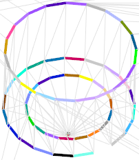
In the last image, the Imprint option was active allowing you to select the delimited areas as individual elements:
Angular deviations
|
Adjacent faces |
This field allows you to set value for the angle between adjacent faces to define whether they are considered as a single face or as individual faces. |
In the following example, the Adjacent face angle was set to 10 in the first image making the function detect a great number of faces. Increasing the angle value to 30 reduces the number of detected faces to 3:
|
Edge propagation |
This field allows you to set a value for the angle between edges to define whether they are considered as a single edge or as individual edges. |
In the following example, the Edge propagation angle was set to 10 in the first image making the function detect a great number of edges. Increasing the angle value to 30 reduces the number of detected edges to 3:
![]() Note: Clicking on the Measurement
Note: Clicking on the Measurement ![]() icon alongside the active value input box displays the Measurement Menu which helps you to define specific points.
icon alongside the active value input box displays the Measurement Menu which helps you to define specific points.
Results
|
Different colours |
Activate this option to display the results in different colours as shown in the above examples. |
|
Colour |
If the Different colours option is not active, the detected edges are displayed with the colour indicated in this colour field. Clicking on the field displays the Colours setting dialog box allowing you to select another colour. |
|
Thickness |
Allows you to set the line thickness to a value between 1 and 7 (default = 4). |
In the following example, the result colour is set to light green and the line thickness to 7:
Information Field
The field at the bottom of the dialog box displays information about missing data, errors or actions.