Layers Structure Tree
After activation of the Layer Management function, the following panel displays a structured tree similar to an assembly tree:
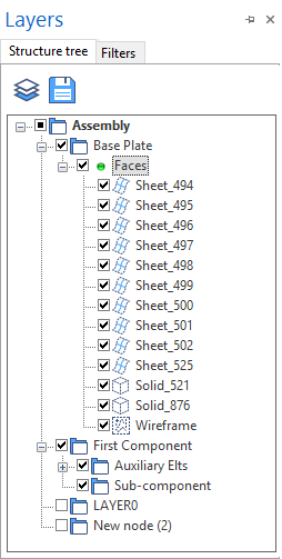
- Next to the Structure tree tab, this panel contains a Filters tab allowing you to set additional filters for entity display in the graphic area. The interaction between the active nodes and these filters defines which entities are actually displayed in the graphic area.
- Under the main Assembly node, you may create nodes and sub-nodes grouping together the components and sub-components consisting of solids and faces as well as auxiliary elements, such as workplanes, wireframe elements, etc.
Toolbar
|
|
Click on this icon to switch to Layers View display. |
|
|
Clicking this icon allows you to save your current node configuration as default system configuration. |
Display
- Clicking the [+] icon alongside a node
 entry allows you to expand the display of the corresponding level showing its contents.
 - Clicking the [-] icon alongside a node entry allows you to collapse the display of the corresponding level hiding its contents.
A node may contain other nodes or the list of entities created in this node such as solids ![]() , surfaces or sheet bodies
, surfaces or sheet bodies ![]() . By default, these entities are named by their geometry type and a number (example: Solid_500). The Wireframe
. By default, these entities are named by their geometry type and a number (example: Solid_500). The Wireframe ![]() entry groups together all the wireframe entities and workplanes stored in the node.
entry groups together all the wireframe entities and workplanes stored in the node.
Visibility
Alongside each entry of the structure tree, a check box allows you to manage the visibility of the corresponding node and/or entity.
- If the check box is checked, the corresponding entity is visible in the graphic area.
- If a black square is displayed in a node check box, only some of the entities in this node are visible.
- Holding the Mouse cursor over visible elements highlights the corresponding entity in the graphic area. If the Mouse cursor is hold over a node, all its visible entities are highlighted.
- If one or more visible entities are selected in the structure tree, they are also pre-selected in the graphic area allowing you to perform actions on them.
Context Menus
Right clicking on an empty space in the panel or on a tree entry displays a context menu allowing you to accomplish a number of actions:
|
Switch to layers view |
This option is only available if the Assembly entry is the active one. It allows you to switch to the Layers View which is an alternative presentation of the layers contained in the project. |
|
Activate node |
This option is only available if there are no more sub-nodes under the selected level. It allows you to activate the node in order to store any newly created entity in it.
|
| Add elements to node |
This option allows you to add elements to the selected node:
|
|
Create new node |
This entry is available if a node entry is active. It allows you to create a new node under the currently active level.
|
|
Delete |
Activate this option to delete the active element:
|
|
Rename |
Selecting this option activates the node name input field allowing you to rename the node. |
|
Copy as MEG |
This option allows you to copy the selected solid and sheet items to the clipboard as MEG (Machining Element Graphics). You may then directly insert them into applications, such as ToolStore, which support the *.meg file format. |
![]() Notes:
Notes:
- The root node Assembly cannot be renamed or deleted.
- Wireframe entries cannot be renamed.
- Two default nodes (LAYER0 and LAYER1) are automatically included when starting a new project.
- The sub-nodes are automatically sorted alphabetically.
- The Undo function is available.
- You may use drag & drop to move entities or nodes to another node if you want to rearrange your structure.
For further information...