Extrude
![]()
The Extrude function allows you to create a solid by moving an element through a distance in a given direction. It also allows you to apply a taper angle to the created solid.
![]() Notes:
Notes:
- You may select and extrude regions (closed areas generated by wireframe elements/edges that lie on the current Workplane). They are selected as faces.
- It is possible to select wireframe elements, faces, sheet bodies, edges and regions to create extrusions.
- When selecting wireframe elements such as lines or arcs, or edges from surfaces or a solid, they will be extruded as sheet elements only.
- Extruding a profile or region allows you to create a solid body.
- To create a solid body from a face or surface/sheet, you may prefer to use the Extrude option in the Move function.
Access
- Click the
 icon in the Solids section of the Designer tab.
 - Activate the Solids tab and then click the icon in the Forms section of the ribbon.
- Type extrude in the Quick Search field and select Extrude from the result list.
In all cases, this opens the Extrude Options tab which is displayed along with the ribbon containing the Environments, Options (either Face Selection Aid or Chain selection), Filters, Selection and Attributes sections if no element was previously selected. In addition, the Extrude dialog box is displayed. ![]() (See dialog box.)
(See dialog box.)

Procedure
- If it was not done previously, using the different selection filter options, select the elements which you want to extrude.
- Select the required options according to the result you want to achieve.
- Using the Distance and Draft angle sliders or the corresponding fields in the dialog box, define the extrusion to apply.
- Validate, either by a Right Mouse click or by clicking the
 icon in the dialog box.
 - You may click the active slider arrow to adjust the value of the corresponding dimension in the value input box of the slider label.
-
You can use simple JavaScript expressions and mathematical formulas to define the required values.
- Clicking on the Measurement
 icon on the slider label or alongside the active value input field in the dialog box displays the Measurement Menu which helps you to define specific points.
 - Pressing the [W] key of your keyboard allows you to toggle between wireframe and shaded preview display of the entity being created.
- If mandatory values are missing or if erroneous values are entered, an exclamation mark
 is displayed in the relevant slider value input box and the background of the corresponding parameter input box in the dialog box is displayed in red..
![]() Notes:
Notes:
Extrude Options
The following options are available in the Extrude dialog box.
Top Toolbar
![]()
![]()
![]()
These two icons at the top of the dialog box allow you to Apply the current values or to Cancel the current function.
Preview generation is Automatic if this option is active in the dialog box menu accessed by clicking on the  icon. If this option is not active, click on the
 ![]() icon. If preview generation is not possible, the icon is greyed out.
icon. If preview generation is not possible, the icon is greyed out.
|
Elements to extrude |
This field lists the identifiers of the selected elements. Clicking on the |
|
Extrude Direction |
The first time you enter the function, the default direction is set to the Z-axis of the current workplane. Then, the function automatically selects the most appropriate direction according to the selected entity. If you do not want to use the default direction, click the
You may also use the Direction definition options that become available on the ribbon at function selection. |
 icon switches back into the selection mode allowing you to modify your selection by selecting/unselecting elements in the graphic area. Use the
![]() Note:
Note:
The application applies the following rules to select the appropriate extrusion direction:
- If you select a planar wireframe element or a planar profile, the extrusion direction is the normal of the plane.
- If you select planar faces or planar sheet bodies, the extrusion direction is the normal of the plane face or body.
- If you select the laminar edge of a planar sheet body, the extrusion direction is the normal of the face on the edge.
- If you select an edge of a planar face of a solid, the extrusion direction is the normal of the face on the edge. In this case, there are two faces attached to this edge and the function uses the direction which is more parallel to the Z-axis of the workplane.
- If you select a vertical element with respect to the XY plane, the direction is the X-axis of the workplane.
-
The extrusion of laminar edges applies the most suitable direction according to the type of selected edge (linear, curve, flat surface, etc.).
Next alternative direction
This field becomes available if entity creation may be done in several directions. It displays the number of possible directions and the currently active one.
To navigate from one direction to another:
- Use the
 and
and  icons alongside this field to respectively move back or forward, or
 - Click the
 icon on one of the distance slider labels to switch to the next possible direction.
In the following example, the profile was selected:

The following images show the different results obtained using the Next alternative direction function:


Parameters
|
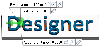
First distance |
If By distance is active in the Options section of the dialog box, this field allows you to enter the first extrusion distance. Its value may be positive or negative. |
|
Second distance |
If By distance is active in the Options section of the dialog box, this field allows you to enter the second extrusion distance. Its value may be positive or negative. The field is not available if the Apply distance on both sides option has been activated. In the graphic area, this distance is represented by a green sphere. |
|
Draft angle |
This field allows you to define a draft angle. A negative angle will expand the reference element to its final size and a positive angle will decrease the size of the reference profile or element. This option also works with open wireframe elements when they are extruded using the By entity option. |
|
Reverse side |
Activating this option or clicking the |
|
Apply distance on both sides |
If this option is active, the value entered for the First distance is applied on both sides of the selected elements. The Second distance field is not available. |
Options
|
Extrusion method |
By distance: Activate this option to define one or two extrusion distances. |
|
By 3D translation: This option allows you to extrude the selected elements along three directions:
In the following example, the profile has been extruded using the slider:
|
|
|
By entity: Activate this option to define the extrusion length by reference entity:
In the following example, the profile has been extruded with respect to a reference point:
|
|
|
Reference Element |
Click the |
|
Extrusion Result |
Extrude as body: For profiles or regions, activating this option allows you to extrude the elements as body. |
|
|
Extrude as sheet: Activating this option allows you to extrude the elements as sheets: |


The following profiles were used for the examples:

Extrude as body option active:

Extrude as sheet option active:

Thicken
The options in this section become available if the Extrude as sheet option is active as the Extrusion result:
|
Thicken extruded bodies |
Activate this option if you want to apply a thickness to the extruded sheet body. In this case, the thickness input fields become available. |
|
Positive/Negative thickness |
The thickness input fields allow you to define the wall thickness to be applied to the sheet body. Alternatively, you may also use the corresponding sliders in the graphic area which are displayed if the Thicken option is active. |
|
Apply thickness on both sides |
Activating this option applies the defined Positive thickness value on both sides of the sheet body. In this case, the Negative thickness field is not available. |
In the following example, for the left profile extruded as sheet, a Positive and Negative thickness has been applied:


Boolean operation
|
Use inner regions |
This option is only active if Extrude as body has been selected in the Extrusion result section. Activating this option applies a simultaneous extrusion of inner and outer profiles. Only the portion included between the profiles is extruded. This option is particularly useful when extruding text for engraving purposes. In the following example, for the text profile to be extruded, this option is not active in the first result illustration but was activated in the second one: |


Merge extrusions | This option allows you to manage the extrusion of "connected" profiles, regions and wireframe elements. If it is not activated, the function extrudes the selected elements as separate entities. If you activate this option, the elements are merged to create a single entity. In the following example, several regions were selected to create individual entities when this option is not active and a single entity when it is active:
|
Automatic solution | Activating this option allows you to automatically perform the most convenient Boolean operation according to the extrusion direction and the resulting intersection with existing bodies. The following rules apply:
|
Boolean operation | This section allows you to select a Boolean operation to apply during solid creation. Select either None, Subtract or Unite. |


Information Field
The field at the bottom of the dialog box displays information about missing data, errors or actions.