Chamfer (Solid)
![]()
The Chamfer function allows you to create chamfers with one or two dimensions with respect to the edges of a solid.
![]() Note: This command may be applied to mesh entities.
Note: This command may be applied to mesh entities.
Access
- In the Designer tab, select
 Chamfers from the drop-down list under the
  icon in the Solids section of the ribbon.
 - Activate the Solids tab and then click on the icon in the Operations section of the ribbon.
-
Type cham in the Quick Search field and select Chamfers from the result list.
In all cases, this opens the Chamfers - Options tab which is displayed along with the ribbon containing the Filters and Selection sections. In addition, the Chamfer dialog box is displayed. ![]() (See dialog box).
(See dialog box).
Procedure
In the following steps, confirmation by Right Mouse click may be required if Multi-select ![]() is active in the Selection options.
is active in the Selection options.
- Using the Edge selection filters, select the edge(s) to which you want to add a chamfer.
- Select the required options according to the result that you want to achieve.
- Using the Distance/Angle slider(s) in the graphic area or the corresponding fields in the dialog box, define the chamfer to apply.
- Validate, either by a Right Mouse click or by clicking the
 icon in the dialog box.
![]() Notes:
Notes:
- You may click the active slider arrow to adjust the value of the corresponding dimension in the value input box of the slider label. You may also define the chamfer value by picking a specific point in the graphic area.
-
You can use simple JavaScript expressions and mathematical formulas to define the required values.
-
Clicking on the Measurement
 icon on the slider label or alongside the active value input field in the dialog box displays the Measurement Menu which helps you to define specific points.
 -
If mandatory values are missing or if erroneous values are entered, an exclamation mark
 is displayed in the relevant slider value input box and the background of the corresponding parameter input box in the dialog box is displayed in red.
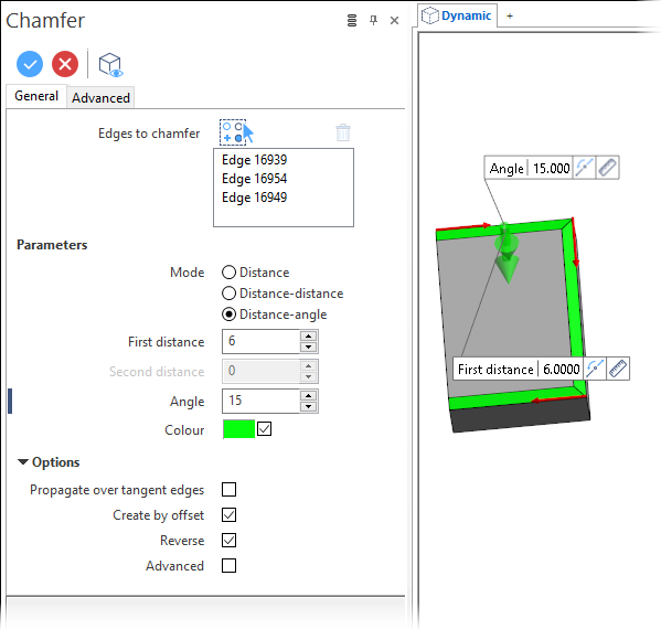
Chamfer Options - General Tab
The following options are available in the General tab of the Chamfer dialog box:
Top Toolbar
![]()
![]()
![]()
These two icons at the top of the dialog box allow you to Apply the current values or to Cancel the current function.
Preview generation is Automatic if this option is active in the dialog box menu accessed by clicking on the  icon. If this option is not active, click on the
 ![]() icon. If preview generation is not possible, the icon is greyed out.
icon. If preview generation is not possible, the icon is greyed out.
Edges to chamfer
The Edges to chamfer field lists the identifiers of the selected edges.
Clicking on the ![]() icon switches back into the selection mode allowing you to modify your selection by selecting/unselecting elements in the graphic area.Use the
icon switches back into the selection mode allowing you to modify your selection by selecting/unselecting elements in the graphic area.Use the ![]() icon (or Right Mouse click) to Validate your selection. The
icon (or Right Mouse click) to Validate your selection. The ![]() icon (or [Esc]) cancels the selection mode.If you want to delete elements within your selection, select the required elements and then click the
icon (or [Esc]) cancels the selection mode.If you want to delete elements within your selection, select the required elements and then click the ![]() icon above the list field. You may use the [Ctrl] + [A] shortcut to select all of the elements.
icon above the list field. You may use the [Ctrl] + [A] shortcut to select all of the elements.
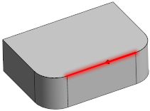
Parameters
To illustrate the different options, the red edge was selected on the following solid:
|
Mode |
This field allows you to define the chamfer creation method:
|
|
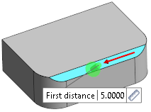
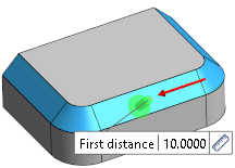
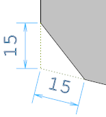
First distance |
This field is always available and allows you to define the (first) chamfer distance with respect to the selected edge(s). If the Distance mode is active, the chamfers are created as follows:
|
|
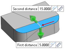
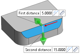
Second distance |
This field is available if the Distance-distance mode has been activated. It allows you to define the second distance with respect to the selected edge(s). Clicking the This is shown in the following example where Reverse has been activated in the second image:
|
|
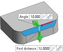
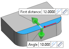
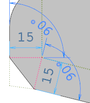
Angle |
This field is available if the Distance-angle option has been activated. It allows you to define an angle in addition to the first distance. Clicking the This is shown in the following example where Reverse has been activated in the second image:
|
|
Colour |
If you want to define a special colour for the chamfers to be created, activate the check box and click the colour field to display the Colour setting dialog box allowing you to select a colour. This was applied to the examples. |
Options
|
Propagate over tangent edges |
Activate this option to propagate chamfer creation over tangent edges:
|
|
Create by offset |
Activate this option to create the chamfer based on offsetting the adjacent faces of the selected edge and applying the chamfer on the resulting projection. In case of faces with 90 degrees there is no difference. In the first image, the following illustration shows the result if this option is not active. In the second image, the option is active:
|
|
Reverse |
This option is available with the Distance-distance and Distance-angle options. It allows you to reverse the direction of application of the two values defined (see illustrations above). |
|
Advanced |
This option can be used when the chamfer creation fails for any reason. It attempts to create the chamfer with lower tolerances and the size of the chamfer could be a little different from the value used but remains acceptable for the user. |
Information Field
The field at the bottom of the dialog box displays information about missing data, errors or actions.
For further information...
Chamfer (Solid) - Advanced Tab