Chamfer dimension
![]()
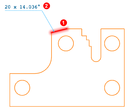
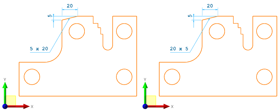
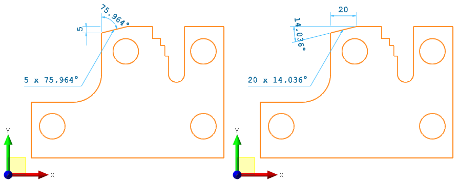
This command allows you to annotate the selected chamfer by choosing which dimensional elements to display:
A leader line is added to the text.
![]() Note:
Note:
This annotation is very similar to the Text leader annotation.
Access
- Click the
 icon from the Simple section of the Annotations tab.
Or
- Type Chamfer in the Quick Search field and select Chamfer dimension.
This opens the Options tab containing the Filters and Attributes sections.
Procedure
- Select the appropriate Filters and Attributes options.
- Pick the chamfer
 to be dimensioned.
 - Identify the application point
 of the chamfer dimension and confirm by clicking the left mouse button.
 -
Turn on/off dimension text underlining by clicking on the Underline
 icon.
icon. - Load the Dimension Properties dialog by clicking on the Properties
 icon or by pressing the [T] Key to enter and configure the dimension after validation. (See Chamfer dimension Properties).
 -
Change the text application point with respect to the leader line (eight different positions) by pressing the Space bar.
-
In a 3D environment it is possible to use the W key to switch the dimension onto a different plane ( XY, ZX or ZY), in relation to the current workplane.
-
Continue to create as many Chamfer dimensions as you need by sequentially selecting all the required chamfers.
- Once the last required chamfer dimension has been defined, click the right mouse button or click on the Apply icon
 to validate.
![]() Note: the position of the dimension is displayed dynamically depending on the mouse position. Before validation, it is possible to perform the following operations from the Filters section of the Options tab:
Note: the position of the dimension is displayed dynamically depending on the mouse position. Before validation, it is possible to perform the following operations from the Filters section of the Options tab:
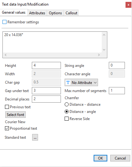
Chamfer dimension Properties
This dialog is loaded during the Chamfer dimensions creation and Chamfer dimension editing.
General values Tab
|
Remember settings |
Activate this option to save your current settings. |
|
Text field |
Enter/Modify the text in this field. You can use keyboard shortcuts to add special characters:
|
|
Height |
Enter the height of characters in this field. |
|
Width |
Enter the width of characters in this field (only for static text). It is disabled if the Static proportional text option is activated. |
|
Char gap |
Enter the distance between each character in this field. It is disabled if the Static proportional text option is activated. |
|
Gap under text |
Enter the distance between the text and the leader in this field. |
|
Decimal places |
Enter the number of decimal places to display. |
| Previous text | Activate this option if you to want to reuse text from the previous chamfer dimension. |
|
Select font |
Click this button to define the font parameters. |
|
Proportional text |
When this option is activated, proportional text is applied meaning that the width of characters is calculated as a ratio relative to the height of characters. |
|
Standard text |
This option allows you to select predefined text in the application:
|
|
String angle |
Enter the angle for the entire string of characters in this field. |
|
Character angle |
Enter the angle of characters in this field (only for static texts). It is disabled if the Proportional text option is activated. |
|
Text attribute |
Select the text attribute in this drop-down list: Underline, Overline, etc. |
| Max number of segments |
Enter the maximum number of segments composing the leader in this field. Note that the maximum number of segments allowed is 3. |
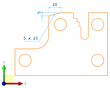
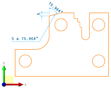
| Chamfer |
Allows you to select the kind of data to be displayed by the dimension:
|
|
Reverse Side |
Select this option to reverse the dimension for asymmetrical chamfers. See example of
|
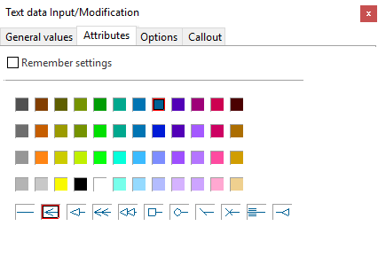
Attributes Tab
|
Remember settings |
Activate this option to save your current settings. |
|
Text colour |
Select the text colour. |
|
Arrow style |
Select the arrow style for the leader. |
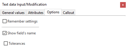
Options Tab
|
Remember settings |
Activate this option to save your current settings. |
|
Show field's name |
Activate/deactivate this option to show/hide the name of the field. |
|
Tolerances |
This option is available when you have selected a circle or circular edge. Activate/deactivate it to show/hide the tolerances defined in the Feature Manager. |
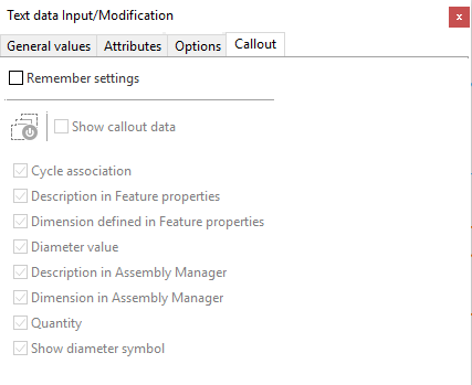
Callout Tab
The ![]() Callout tab is greyed out since it does not affect this annotation.
Callout tab is greyed out since it does not affect this annotation.
Editing Chamfer dimensions
- See Edit dimension.