Boss
Procedure
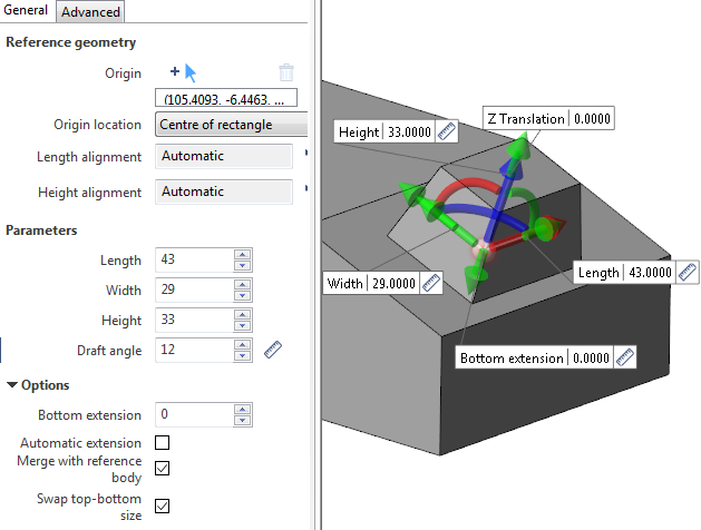
Reference Geometry
- Select the appropriate Filters option.
- Click on the boss origin point on the model. This can be a point or an intersection of 2 segments.
- Select the Origin location from the corresponding drop-down list:
- Bottom left corner.
- Centre of rectangle.
- X axis edge centre.
- Y axis edge centre.
- If necessary, define the Length alignment.
- If necessary, define the Height alignment.
Length/Height Alignment
- Click the
 icon.
icon. - Select the corresponding direction using the Options and Filters.
- Right click to validate.
Cancelling Alignment
- Click the
 icon next to the corresponding alignment.
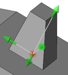
Boss with height aligned to a selected edge (1 in the image below):
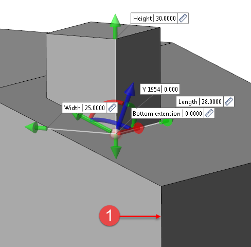
In this example, the Workplane Axis Marker indicates the initial orientation of the boss (normal to the selected surface).
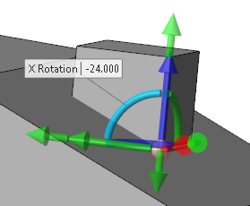
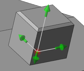
Rotation
You can rotate the boss on the origin point around the 3 axes of the Workplane Axis Marker:
- By dragging the X (red), Y (green) and/or Z (blue) arc in the graphic area.
- By entering the rotation value in the X Rotation, Y Rotation and/or Z Rotation field in the graphic area.
Boss rotated by -24° around the X axis:
Translation
You can translate the boss from the origin point along the 3 axes of the Workplane Axis Marker:
- By dragging the X (red), Y (green) and/or Z (blue) arrow in the graphic area.
- By entering the rotation value in the X Translation, Y Translation and/or Z Translation field in the graphic area.
Boss translated by 10 mm along the X axis:
![]()
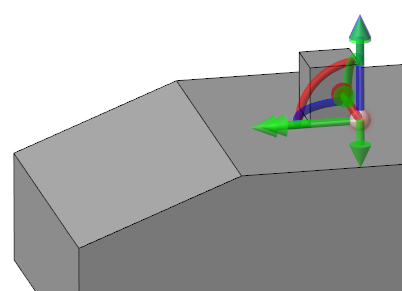
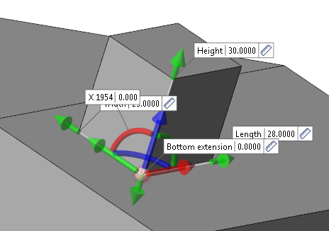
Free Movement
You can move the boss from the origin point along each side of the model. This does NOT work if the Merge with reference body option is activated.
- Click the grey sphere of the Workplane Axis Marker.
- Move your cursor along the model.
- Click the model on the required position to validate.
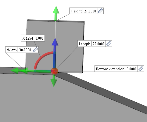
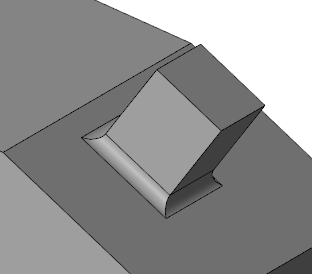
Boss Initial Position:
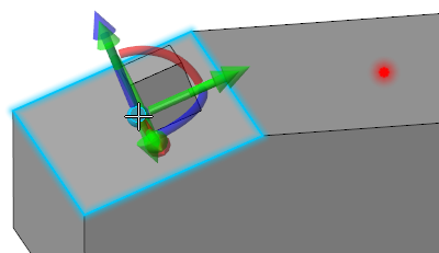
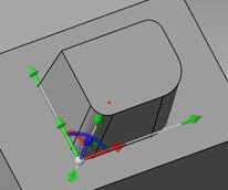
Moving the Boss:
Parameters
- Define the boss length:
- By dragging the Length arrow in the graphic area.
- By entering the value in the Length field in the graphic area or in the dialog box.
- By clicking on the Measurement
 icon, in the graphic area or in the dialog box (next to the active field), and taking measurements.
 - Define the boss width:
- By dragging the Width arrow in the graphic area.
- By entering the value in the Width field in the graphic area or in the dialog box.
- By clicking on the Measurement icon, in the graphic area or in the dialog box (next to the active field), and taking measurements.
- Define the boss height (positive value for a boss; a negative value will create a pocket):
- By dragging the Height arrow in the graphic area.
- By entering the positive value in the Height field in the graphic area or in the dialog box.
- By clicking on the Measurement icon, in the graphic area or in the dialog box (next to the active field), and taking measurements.
- If necessary, define the boss draft angle:
- By entering the value in the Draft angle field in the dialog box. The value cannot be negative.
- By clicking on the Measurement icon in the dialog box (next to the active field), and taking measurements.
Boss with draft angle applied on top surface:
In the above example, the Swap top-bottom size option is activated indicating that the draft angle is applied at the top of the boss. If this option is not activated, the draft angle is applied from the bottom of the boss.
![]() Notes:
Notes:
-
You can use simple JavaScript expressions and mathematical formulas to define the required values.
-
Pressing the [W] key of your keyboard allows you to toggle between wireframe and shaded preview display of the entity being created.
Options
- If necessary, define the boss bottom extension:
- By dragging the Bottom extension arrow in the graphic area.
- By entering the value in the Bottom extension field in the graphic area or in the dialog box.
- By clicking on the Measurement icon, in the graphic area or in the dialog box (next to the active field), and taking measurements.
- If necessary, activate the Automatic extension option to automatically adjust the bottom extension value.
- Activate the Merge with reference body option if you want to perform a boolean operation: Unite in the case of a boss
- Activating or deactivating the Swap top-bottom size option determines how a Draft Angle is applied.
Bottom extension
This parameter allows you to extend the boss to a surface which may be below the boss origin location, for example, if the origin is positioned on the edge of a chamfer.
No bottom extension value:
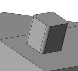
Bottom extension value defined:

Blends/Chamfers
Corners
This parameter allows you to apply blends/chamfers to the corner between each wall of the boss:
- Activate the Chamfer option if you want to create chamfers. Otherwise, blends will be created.
- Enter the chamfer length or corner radius in the Value field.
Boss with corner blends:
Top-Bottom
This parameter allows you to apply blends/chamfers to the top of the boss:
- Activate the Chamfer option if you want to create chamfers. Otherwise, blends will be created.
- Enter the chamfer length or corner radius in the Value field.
Boss with top chamfer:
Connection
This parameter allows you to apply blends/chamfers to the connection between the model and the boss:
- Activate the Chamfer option if you want to create chamfers. Otherwise, blends will be created.
- Enter the chamfer length or corner radius in the Value field.
Boss with connection blends:
Advanced Tab
This tab allows you to apply different draft angles on each wall of the boss and to apply different blends/chamfers to each edge of the boss.
Draft angle
- Activate the Different draft on faces option.
- Enter the different draft angle values in the Angle face X-, Angle face X+, Angle face Y- and Angle face Y+ fields.
Boss with different draft angle values:
Corners blend/chamfer
- Activate the Different blend/chamfer on edges option.
- Enter the different blend/chamfer values in the Edge X-Y-, Edge X+Y-, Edge X+Y+ and Edge X-Y+ fields.
Boss with three different blends on corners:
Hiding Labels in the Graphic Area
Activating the Label auto hide option allows you to hide the labels in the graphic area.
Preview
Preview generation is Automatic if this option is active in the dialog box menu accessed by clicking on the  icon. If this option is not active, click on the
 ![]() icon. If preview generation is not possible, the icon is greyed out.
icon. If preview generation is not possible, the icon is greyed out.
Validation
Validate, either by a Right Mouse click or by clicking the ![]() icon in the dialog box.
icon in the dialog box.
For further information...