Boolean Operations
![]()
This function allows you to execute Boolean operations between a combination of target and tools which can be solids, sheets or mesh entities.
![]() Notes:
Notes:
- The Unite and Subtract operations are directly available when creating basic solid forms, such as Cuboid, Cylinder, Prism, etc.
Access
- In the Designer tab, click the
 icon in the Solids section of the ribbon.
 - In the Surfaces tab, click the icon in the Operations section of the ribbon.
- In the Solids tab, click the icon in the Boolean section of the ribbon.
- Type bool in the Quick Search field and select Boolean from the result list.
In all cases, this opens the Boolean Options tab which is displayed along with the ribbon containing the Filters section. In addition, the Boolean operation dialog box is displayed. ![]() (See dialog box.)
(See dialog box.)
Procedure
In the following steps, confirmation by Right Mouse click may be required if Multi-select ![]() is active in the Selection options.
is active in the Selection options.
- Select the Target body. This may be a single sheet or solid body.
- Using the appropriate Selection and Filter functions, select the Tool bodies (sheet and/or solid bodies).
- Select the required options according to the result you want to achieve.
- Validate, either by a Right Mouse click or by clicking the
 icon in the dialog box.
![]() Notes:
Notes:
- The Boolean operation is computed with respect to the material side of a body. You may use the Orient surfaces function to adjust the orientation of a sheet body.
-
You can use simple JavaScript expressions and mathematical formulas to define the required values.
-
Clicking on the Measurement
 icon on the slider label or alongside the active value input field in the dialog box displays the Measurement Menu which helps you to define specific points.
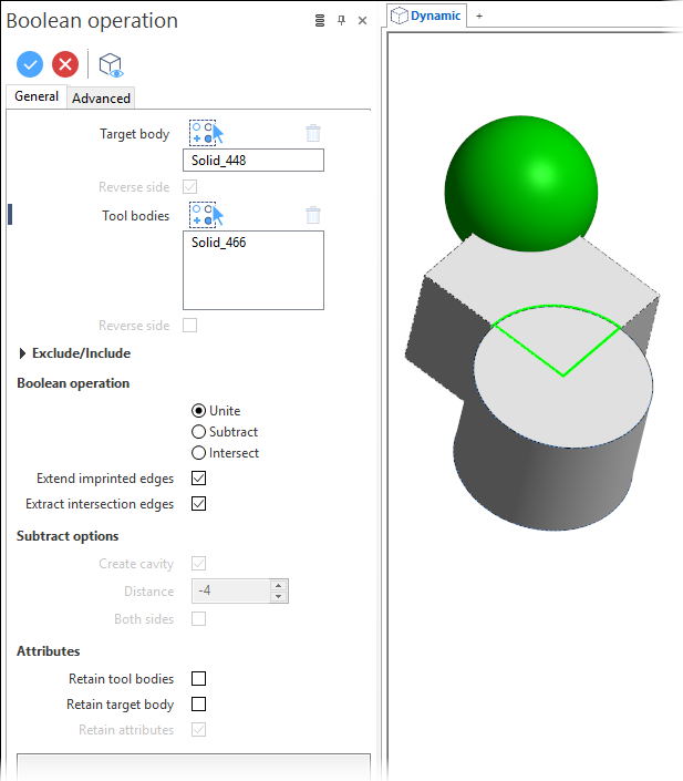
Boolean Operation Options - General Tab
The following options are available in the General tab of the Boolean operation dialog box:
Top Toolbar
![]()
![]()
![]()
These two icons at the top of the dialog box allow you to Apply the current values or to Cancel the current function.
Preview generation is Automatic if this option is active in the dialog box menu accessed by clicking on the  icon. If this option is not active, click on the
 ![]() icon. If preview generation is not possible, the icon is greyed out.
icon. If preview generation is not possible, the icon is greyed out.
|
Target body |
This field displays the identifier of the selected Target body. This can be a sheet or a solid body. |
|
Tool bodies |
This fields lists the identifiers of the selected Tool bodies. This can be one or several solid and/or sheet bodies. |
|
|
For both: Clicking on the |
|
Reverse side |
This option is available for the Target body if it is a sheet and for the Tool bodies if only sheet bodies are selected. Activating this option allows you to change the 'material' side of the bodies before execution of the Boolean operation thus avoiding the use of the Orient surfaces command. |
 icon switches back into the selection mode allowing you to modify your selection by selecting/unselecting elements in the graphic area. Use the
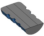
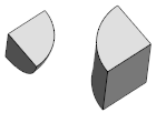
 The example images illustrate the use of the Reverse side option. The grey solid and the blue sheet body (with orange backface colour) are used as Target and Tool bodies:
Boolean operation: Unite
The result is a sheet body.
| Reverse side NOT active: | Reverse side active: |
|
|
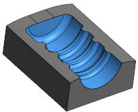
Boolean operation: Subtract
In the following examples, the solid body was selected as the Target and the sheet body as the Tool:
The result is a solid body.
| Reverse side NOT active: | Reverse side active: |
|
|
Exclude/Include
This section becomes available if Unite is selected as the Boolean operation. It allows you to define the regions to keep or to reject by selecting faces included in such regions.
|
Faces |
This field lists the identifiers of the selected faces. Clicking on the |
|
Exclude / Include |
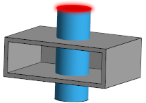
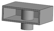
Activate the corresponding option depending on whether you want to include or exclude the regions defined by the selected faces. In the following example, the grey solid is the target body, the blue one the tool body and the red highlighted face is selected.
The first image hereafter shows the result if Exclude is active, the second image, if Include is active:
|
Boolean operation
This section allows you to select the Boolean operation to be made.
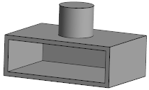
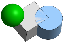
The following solid bodies have been used to illustrate these operations, where the grey cuboid was selected as the target body and the green sphere and the blue cylinder as the tool bodies:
|
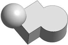
Unite |
This option unites the selected entities to a single body.
|
|
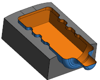
Subtract |
This options removes the intersecting portions of the tool entities from the target body.
|
|
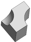
Intersect |
This option keeps only the intersecting portions between the target and tool entities.
|
|
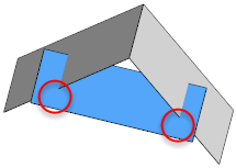
Extend imprinted edges |
In some cases, the intersection between the selected bodies does not produce a complete cut on the faces. In this case, the operation cannot be executed. If this option is active, the system tries to extend the imprinted edges in order to obtain a complete cut of the faces. In the following example, the grey sheet is the target and the blue sheet the tool body. As there is no complete intersection, as shown by the red circles, the operation cannot be made:
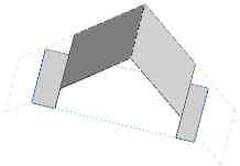
If this option is active, Unite produces the result shown in the image hereafter:
Depending on initial geometry definition, you may have to activate the Reverse side option for either the target body or the tool body elements to obtain the desired result. |
|
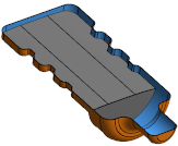
Extract intersection edges |
Activate this option if you want to extract the intersection edges between the target and the tool body. This is shown in the following image:
|
Subtract options
The following options become available if Subtract is selected as the Boolean operation.
|
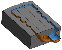
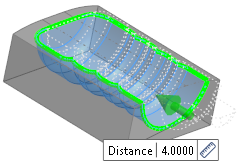
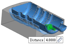
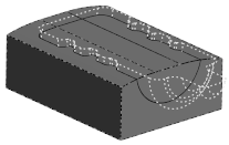
Create cavity |
If activated, this option allows you to create a cavity by adding an offset value in the Distance field:
|
|
Distance |
If the Create cavity option is active, enter the offset value in this field. |
|
Both sides |
If Create cavity is not active, this option allows you to keep both sides if the target is cut by sheet bodies.
|
Attributes
The following options become available if Subtract is selected as the Boolean operation.
|
Retain tool bodies |
If this option is active, the tool bodies are retained. If not active, the tool bodies are removed. |
|
Retain target bodies |
If this option is active, the target bodies are retained. If not active, the target bodies are removed and the newly created bodies inherit the attributes from the target bodies. In this case, body display is transparent during function execution. |
|
Retain attributes |
This option becomes available if the Retain target bodies option is active. If enabled, the newly created entity will have the same attributes (colour, transparency, etc.) as the initially selected target bodies. If this option is not active, the default attributes are applied. |
Information Field
The field at the bottom of the dialog box displays information about missing data, errors or actions.
For further information...
Boolean Operation - Advanced Options