2D Drawing - View
![]()
You can create different types of view (Top, Bottom, Isometric,....) in relation to one Origin defined in the graphic area.
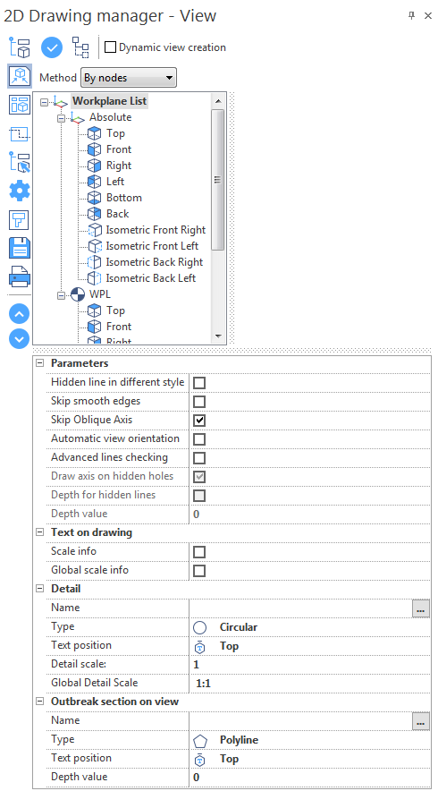
Creating a View
- Define the view parameters in the dialog box.
- Select a view in the workplane list of the 2D Drawing Manager.
- Click the
 icon at the top of the dialog box.
 - Click in the graphic area to position the selected view
Or
- Define the view parameters in the dialog box.
- Right click on a view in the workplane list of the 2D Drawing Manager.
- Click in the graphic area to position the selected view
![]() Notes:
Notes:
- You can click the
 icon to expand/collapse the workplane list.
 - You can use the Method drop-down list to filter the elements to be included in the 2D Drawing: by nodes, by parts or by selection in the graphic area.
Dynamic View Creation
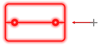
Once you have created the first view in the graphic area, you can automatically create other views, based on this first view.
- Activate the Dynamic view creation option at the top of the dialog box.
- Activate the Automatic view orientation option in the Parameters section of the dialog box.
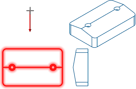
- Click the icon at the top of the dialog box.
- Select the reference view in the graphic area.
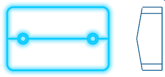
- Drag your cursor around the selected reference, to obtain a preview of the view direction.
- Click to validate the view direction.
- Click a point to position the view.
- Repeat steps 4 to 7 to create as many views as required.
- Right click in the graphic area to validate.
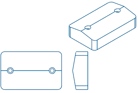
In the example below, we have created a top view that has been selected as a reference view for dynamic view creation:
|
Right view preview: |
Result: |
|
|
|
|
Isometric front right view preview: |
Result: |
|
|
|
|
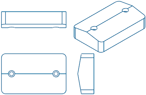
Top view preview: |
Result: |
|
|
|
Configuration
Parameters
|
Hidden line in different style |
Each view shows the lines that are not visible as dotted lines. Activate this option to create views without lines that are not visible. |
|
Skip smooth edges |
Smooth edges are for example edges of a blend with the adjacent faces (tangent edges). Activate this option if you do not want smooth edges to be represented on the created views. |
|
Skip Oblique Axis |
Activate this option to create views without the axis of the holes that are NOT perpendicular to the direction of the view/section. |
|
Activate this option to automatically align the newly created view/section to the reference view. |
|
|
Advanced lines checking |
Activate this option to improve the quality of the view/section to be generated. As this option uses a different function for the calculation of hidden lines, the time needed to view the final result will be longer. You can activate it if your model has intersecting bodies, meaning that the hidden line calculation will need to be more advanced. |
|
Draw axis on hidden holes |
This option is available when the Hidden line in different style option is enabled. Activate this option to draw axes on hidden holes. |
|
Depth for hidden lines |
This option is available when the Hidden line in different style option is enabled. Activate this option to enable the Depth value field for the hidden lines representation. |
|
Depth value |
Enter the depth value for the hidden lines representation. This allows you to represent the hidden lines of the part only for that depth value and the lines that are outside of this value will be ignored. In this way, the representation of the part with hidden lines will be clearer. |
Text on drawing
These options allow you to place the text with the scale information on views, sections and details
|
Scale info |
Text information relating to the scale of the view/section/detail. |
|
Global scale info |
Scale of the view/section/detail according to its scale and the global scale. |
Example:
For a view with scale = 0.5 and placed in a page with Global Scale = 0.4, the text info will be:
- Scale info: 1:2
- Global scale (plotting) info: 1:5
The Scale applied to the view/section/detail will be automatically considered by the system when dimensioning elements belonging to the detail.
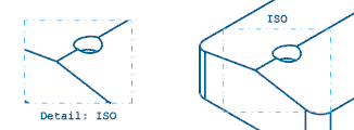
Detail
These parameters allow you to create a detailed view of a particular area on a view/section:
|
Name |
Enter the name of the detailed view in this field. |
|
Type |
|
|
Text position |
|
|
Detail scale |
Enter the scale for the detailed view in this field. |
|
Global Detail Scale |
This field indicates the global detail scale, according to the defined scale. |
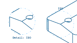
Creating a Detailed View
Circular View:
- Select the Circular option from the Type drop-down list.
- Click the [...] icon next to the Name field.
- Select a view of the 2D Drawing.
- Click the centre point of the detailed view in the graphic area.
- Click the second point to determine the radius of the circular view.
- Click a point on the graphic area to position the detailed view.
Rectangular View:
- Select the Rectangular option from the Type drop-down list.
- Click the [...] icon next to the Name field.
- Select a view of the 2D Drawing.
- Click a point to define the first corner of the detailed view in the graphic area.
- Click a second point to define the opposite corner of the detailed view.
- Click a point on the graphic area to position the detailed view.
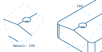
Polygonal View:
- Select the Polyline option from the Type drop-down list.
- Click the [...] icon next to the Name field.
- Select a view of the 2D Drawing.
- Click a point to define the first corner of the detailed view in the graphic area.
- Click other points to define the other corners of the detailed view.
- Right click to validate the polygonal view.
- Click a point on the graphic area to position the detailed view.
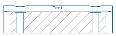
Outbreak section on view
These parameters allow you to create partial section views of a particular area on a view/section:
|
Name |
Enter the name of the outbreak section in this field. |
|
Type |
|
|
Text position |
|
|
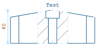
Depth value |
Enter the depth of the outbreak section in this field. |
Creating an Outbreak Section
Rectangular Outbreak Section:
- Select the Rectangular option from the Type drop-down list.
- Click the [...] icon next to the Name field.
- Select a view of the 2D Drawing.
- Click a point to define the first corner of the outbreak section in the graphic area.
- Click a second point to define the opposite corner of the outbreak section.
Polygonal Outbreak Section:
- Select the Polyline option from the Type drop-down list.
- Click the [...] icon next to the Name field.
- Select a view of the 2D Drawing.
- Click a point to define the first corner of the outbreak section in the graphic area.
- Click other points to define the other corners of the outbreak section.
- Right click to validate the polygonal outbreak section.
2D Drawing Tab
This tab of the ribbon contains the following icons:
|
|
Click this icon to update a selected view/section with new parameters. |
|
|
Click this icon to update all views/sections with new parameters. |
|
|
Click this icon to access the View Properties dialog box. |
|
|
Click this icon to access the Page Properties dialog box. |
For further information...